Read this article in 中文 Français Deutsch Italiano Português Español
Rethinking torsional stiffness for the variable-speed era

August 25, 2026
 Steve Pennington, Global Engineering Coupling Manager at John Crane. (Photo: John Crane)
For decades, drivetrain torsional analysis has relied on a fundamental assumption: the torsional stiffness of a coupling is a fixed value.
That assumption has served the rotating equipment industry reasonably well, but as compressor trains become increasingly sophisticated—particularly with the widespread adoption of variable frequency drives (VFDs), electric motors and wider operating envelopes—it has also become one of the industry’s biggest limitations.
According to Steve Pennington, Global Engineering Coupling Manager at John Crane, the gap between modeled performance and actual operating behavior has become increasingly apparent.
“We were seeing an increase in questions around torsional stiffness based on variable frequency drives and the accuracy of the calculations,” Pennington said. “Traditionally, ourselves and the whole coupling community supplied one torsional stiffness value, but we had a few applications where the value wasn’t correlating as accurately as we would have liked in the field.”
That realization prompted a three-year research effort that has resulted in what John Crane describes as an industry-first validated methodology for drivetrain analysis. Rather than treating coupling stiffness as constant, the new approach models stiffness as a dynamic characteristic that changes with torque and operating conditions. The methodology has been validated through analytical modeling, laboratory testing and multiple field installations, significantly improving the correlation between predicted and measured drivetrain behavior.
According to John Crane, the improved drivetrain models can reduce commissioning risk, improve reliability and help identify potential resonance issues before equipment enters service.
Why traditional models fall short
Torsional analysis is a critical part of designing rotating equipment trains. Engineers evaluate how motors, turbines, gearboxes, couplings and driven equipment behave together to ensure the system’s natural frequencies do not coincide with operating speeds.
Historically, coupling manufacturers have supplied a single torsional stiffness value for use in these analyses.
The problem, Pennington explained, is that couplings do not actually behave that way.
“We stumbled upon a nonlinear response,” he said. “That led us to believe we should be giving multiple torsional stiffness values instead of just one.”
Further testing uncovered an even more significant finding.
“When we saw very small changes in torque, the coupling started using its hysteresis behavior to damp out the system,” he said. “That meant we could accurately predict torsional stiffness for a particular torque value, allowing customers to operate much closer to natural frequencies while using the coupling’s own damping capability.”
In practical terms, Pennington said, the coupling’s stiffness changes throughout its operating range. Instead of behaving like a rigid spring with one constant characteristic, it responds differently during startup, steady-state operation and changing load conditions.
John Crane now defines these regions separately, distinguishing between an initial “dynamic stiffness” region and the traditional “static stiffness” values used during normal operation.
Variable-speed systems raise the stakes
Pennington said the growing use of variable frequency drives throughout the natural gas industry has increased the need for more accurate drivetrain analysis because compressor trains now operate across a much wider range of speeds and torque conditions.
 John Crane said its new dynamic coupling methodology improves drivetrain modeling by accounting for torque-dependent stiffness, helping OEMs reduce commissioning risk and improve reliability. (Image: John Crane)
Unlike fixed-speed compressor trains, variable-speed systems operate across a broad range of speeds and torque conditions. That flexibility improves efficiency and process control, but it also increases the likelihood that equipment will pass near torsional natural frequencies during startup, shutdown or load changes.
“The more complex drives—the low-speed, high-speed coupling applications and multiple drivetrains—are where we can really benefit,” Pennington said. “We can now pinpoint torsional stiffness for a particular torque over the operating range.”
Rather than forcing engineers to work with an averaged stiffness value, Pennington said the methodology provides multiple operating points, enabling much more representative system models.
“We can make the torsional analysis super accurate,” he said. “The only limitation now is how much information today’s analysis software can practically use.”
From laboratory to field
John Crane did not introduce the methodology until it had been validated in actual operating equipment.
Development began with conventional static testing before engineers designed a unique dynamic test rig capable of measuring torsional stiffness while the coupling was rotating.
“We came up with a very unique solution to measuring torsional stiffness dynamically,” Pennington said. “Using optical measurements on our dynamic test rig, we were able to measure torsional stiffness dynamically, which is quite unique.”
The company then compared those results against analytical models before validating the approach in operating machinery.
“We tested statically and dynamically, got correlation with finite element analysis and then, more importantly, extremely accurate correlation with what went on site,” Pennington said. “We’ve had strain gauges on site measuring the torsional forces, and we’re within a couple of percent of where we predicted we’d be. For drivetrain analysis, that’s exceptionally close.”
To date, the methodology has been successfully deployed on four customer applications.
In one case, a drivetrain repeatedly encountered a torsional critical speed during operation.
“Previously, we were moving into a first natural critical and had to stop the machinery,” Pennington said. “We changed the parameters using the new methodology, and now the equipment operates at exactly the same speed without hitting the critical frequency.”
Reducing commissioning surprises
For compressor packagers and EPC contractors, commissioning is often where deficiencies in drivetrain modeling become painfully obvious.
Unexpected resonance problems discovered during startup can delay projects, require redesigned couplings or force operating restrictions until permanent solutions are implemented.
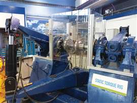 John Crane said it did not introduce the methodology until it had been validated in actual operating equipment. Development began with conventional static testing before engineers designed a unique dynamic test rig capable of measuring torsional stiffness while the coupling was rotating. (Image: Static Rig)
Pennington believes improving prediction accuracy can significantly reduce those risks.
“By the time it gets to commissioning, we’re supplying something we know is going to work,” he said. “In the past we’ve had situations where we had to go back and manufacture different couplings to change the torsional characteristics. Now we’ve already proven the design before commissioning.”
Pennington said that confidence is particularly valuable on large LNG, pipeline compression and power generation projects where delays can have substantial financial consequences.
He also said the methodology improves collaboration among OEMs by providing more representative drivetrain information during the design phase, helping reduce integration issues before equipment reaches the field.
What about existing equipment?
One of the first questions John Crane received after introducing the methodology concerned legacy equipment.
If engineers have been using a simplified stiffness model for years, does that mean existing compressor trains are at risk?
According to Pennington, the answer is no.
“The existing fleet is fine,” he said. “We’re not changing anything that’s already there. We’re enhancing the understanding and providing greater accuracy.”
Instead, he said, the additional information becomes most valuable when operators upgrade equipment, retrofit VFDs or modify operating conditions.
“If you want to improve efficiency, change the drivetrain or operate in a different range, we now have more knowledge about the torsional stiffness and can work much more accurately,” he said.
Pennington said retrofit projects can particularly benefit from the methodology because historical drivetrain information is often incomplete.
More data—and more opportunities
The methodology is currently being rolled out to additional OEMs following successful implementation with an initial customer.
Not surprisingly, the increased accuracy also creates a new challenge: information overload.
“We actually have four different points on the torque curve,” Pennington said. “The challenge now is that we’re almost overloading OEMs with information because today’s software can’t always use all of it.”
Even so, Pennington expects analysis tools to evolve alongside the methodology.
Looking ahead, he said artificial intelligence could eventually help engineers interpret increasingly complex drivetrain data, although the immediate focus remains on further refining the underlying models.
“We’ve got another year of testing planned,” he said. “There are another three parameters we want to review. It’s all about increasing the accuracy even further.”
A shift in drivetrain engineering
Looking ahead, Pennington believes increasingly sophisticated drivetrain analysis will become more important as compressor packages incorporate variable-speed motors, electric drives and more advanced control strategies. He said better correlation between modeled and actual operating behavior can help OEMs and operators reduce commissioning issues while improving long-term reliability.
Pennington also said the work challenges one of the rotating equipment industry’s longstanding assumptions—that coupling torsional stiffness can be represented by a single constant value. According to him, incorporating multiple operating points into drivetrain models provides a more representative picture of how couplings behave under real operating conditions.
John Crane said the methodology is intended to provide engineers with more accurate drivetrain information during the design process, particularly for new installations, equipment upgrades and variable-speed applications. The company said the objective is to reduce commissioning surprises, improve system performance and give OEMs and end users greater confidence that modeled drivetrain behavior will closely match actual operating conditions.

CONNECT WITH THE TEAM