Read this article in 中文 Français Deutsch Italiano Português Español
Cooper’s transition from steam to gas
May 09, 2026
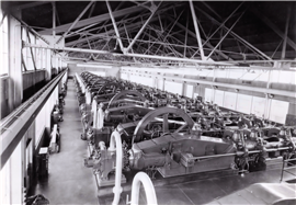 A line of ten Cooper-Bessemer Type 22 twin tandem gas engine-compressors at a gas pipeline transmission station.
The C. & G. Cooper Company, founded in 1833, had built approximately 15,000 steam engines throughout its history into the early 1900s. It was a leading manufacturer of large Corliss steam engines, but Cooper faced a crossroads as steam turbines seemed destined to dethrone them. With large engines fueled by natural gas becoming successful in the mushrooming steel industry and showing promise for the compression of natural gas in pipelines, the company decided to evolve into the production of natural gas internal combustion reciprocating engines.
Although Cooper had built several large gas engine-compressors for the Snow Steam Pump Works, it did not introduce a horizontal integral gas engine-compressor of its own design until 1909. In 1911, Cooper built three 305 hp (227 kW), 125 rpm, 21 in. (533 mm) bore x 24 in. (610 mm) stroke single-throw tandem double-acting engine-compressors. In the four-year period from 1912 through 1915, more horizontal configurations were developed, and 44 more units were produced. The largest were 965 hp (720 kW), 107 rpm, 21.5 in. (546 mm) bore x 42 in. (1067 mm) stroke and 1300 hp (969 kW), 94 rpm, 24 in. (610 mm) x 48 in. (1219 mm) twin-tandem engine-compressors. The first 19 in. (483 mm) bore x 24 in. (610 mm) stroke and 21.5 in. (546 mm) bore x 36 in. (914 mm) stroke horizontal gas engine-compressors, predecessors of the Types 19 and 22, respectively, were built in 1913. These two models would be popular for the next three decades. Prior to 1913, Cooper engine-compressors were equipped with other manufacturers’ compressor cylinders. But Cooper soon developed its own line of compressor cylinders, which became the standard for pipeline applications, even used on competitors’ gas engines.
The horizontal double-acting, four-cycle power cylinder design of Cooper’s gas engine-compressor was a logical development from its wide steam engine experience for industrial applications. Many elements of steam engine design, such as the main frame, crankshafts, flywheels and crossheads were incorporated almost unchanged into the horizontal gas engine. The type of engine that was to become predominate was the four-cycle, double-acting, tandem horizontal engine. The double-acting cylinders delivered power to both sides of the piston in a single cylinder. By connecting the double-acting power cylinders end-to-end with an intermediate distance piece, it was possible to have four power ends per crank throw. The outer end was supported by a tail guide. And by locating a mirror image twin unit on the other side of the flywheel, a total of eight power ends became available for driving two compressor cylinders on the opposite end of the frames. These two sides were joined with a crankshaft having a crank on both sides with the flywheel supported in the center of the crankshaft as can be seen in the units in Fig. 1.
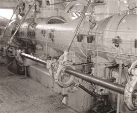 Original Cooper Type 22 gas engine-compressor with eccentrics and push rods, 1922.
When a smaller power unit was desired, the user would order a single tandem engine. This consisted of two power cylinders on a common frame, flywheel and crankshaft with only one crank. The outer end of the crankshaft was supported by a large pedestal bearing.
Sometimes, a user would purchase a single tandem engine and later convert it to a twin tandem by adding the other side and a new crankshaft.
In steam engine practice, it was usual to drive the compressor from the tail-rod crosshead which supported the outer end of the power piston rod, and some early Cooper steam engine gas compressors were built in this design. However, with gas engines, it was more common to put the compressor on the crank end of the engine as shown in Fig. 2 taken from a 1920 catalogue. This required an extension of the main frame to provide an additional crosshead and a set of tie rods to direct drive this crosshead which, in turn, drove the compressor piston rod. Although this added to the cost of the engine, it provided a cleaner design of the station as it allowed all the gas suction and discharge lines to be located one side of the building and the engine air intake and exhaust piping to be on the other side.
A radical departure from steam engine design was the necessity for cooling not only the cylinder walls, but also removing heat from the pistons and rods. This was accomplished by drilling a central passage the length of the piston rod and casting hollow pistons to provide internal cooling chambers. Cooling water was then admitted to the center crosshead by means of a telescoping joint where it flowed through each piston and rod and then exited at the front crosshead and rear tail-rod support into a trough in the casting.
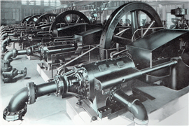 The compressor ends of a line for five Cooper horizontal gas engine-compressors, 1919.
Evidently the early 42 and 48 in. (1067 and 1219 mm) stroke twin tandem designs proved rather unwieldy for transport and installation at remote field locations, as units after 1917 were built with 24 and 36 in. (610 and 914 mm) strokes. In 1917, Cooper introduced its famous Type 22, a 36 in. (914 mm) stroke twin tandem machine rated initially at 970 hp (723 kW) and later at 1100 hp (820 kW). By the early 1920s, it had become the gas engine-compressor of choice for most gas pipelines.
After World War I, Hewitt A. Gehres joined Cooper as chief engineer, a position that he would hold until 1956. The company was struggling to make the large horizontals profitably, and Gehres went about completely redesigning the Type 22 gas engine-compressor. The early Cooper gas engines copied many features of a European design. For example, the intake and exhaust valves were operated from a horizontal lay shaft which ran the length of the engine. The original engines had big eccentrics with two push rods as shown in the c.1922 engine-compressor in Fig. 3. These were replaced with camshafts and rollers cams, shown in Fig. 4, that gave a quicker opening and closure of the valves, increasing the 125 rpm engine rating to 1000 hp (746 kW). Incidentally, the early 1920s Type 22 machines in Fig. 3 and Fig. 4 operated reliably until 2013 at Columbia Gas’ gas storage station in Rockport, West Virginia.
Original Cooper Type 22 gas engine-compressor with eccentrics and push rods, 1922.
Gehres cut so much cost out of the engines that no one else could compete with the Cooper Type 22. In the succeeding years, Type 22 twin tandem engine-compressors were favored in pipeline service by companies such as Ohio Fuel Supply, United Fuel Gas, Magnolia Gas and Columbia Gas & Electric. Fig. 1 shows a line of ten Type 22 horizontal gas engine-compressors providing 22,000 hp (16,412 kW) of compression at a gas pipeline transmission installation in the late 1920s.
The story of Cooper horizontal gas engine-compressors will conclude in the next issue.
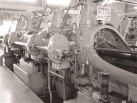 Improved Cooper Type 22 gas engine-compressor with camshafts and rollers, 1924.

CONNECT WITH THE TEAM