What is the ideal inlet piping length for centrifugal compressors?
August 15, 2022
Flow distribution at the compressor inlet flange is critical to both machine performance and accurately measuring the inlet conditions. A flow distribution that is radially uniform is preferred to minimize the aerodynamic effects at the compressor inlet.
Non-uniform velocity or pressure fluctuations, also called distortions, increase aerodynamic losses at the blade leading edge and can lead to unstable compressor operation. Fortunately, fluctuations are self-correcting so that a uniform flow can be achieved given enough length of straight pipe.
However, the length of straight pipe depends on the magnitude of the velocity and pressure fluctuations. For compressors, a long length of straight pipe at the inlet is not always possible due to space constraints and process piping that usually contains valves, elbows, and pipe expansions. The primary concern is to identify the length of straight pipe needed to minimize inlet flow distortions.
This article summarizes practical guidelines for piping configurations that will not adversely affect compressor performance, while recognizing that piping must be minimized for economic plant design. It presents a basic approach to the analysis of piping configurations.
As a starting point, the American Society of Mechanical Engineers (ASME) Performance Test Code (PTC) on Compressors & Exhausters can be used to determine the length of straight pipe upstream of the compressor inlet to provide uniform flow for test measurements.
The PTC [1] requires a minimum of three diameters of straight pipe between an elbow and the compressor inlet and longer lengths up to 10 or more diameters for piping smaller than 24-inch diameter, axial inlets, or other upstream disturbances. A second recommendation, which is part of Elliott Group’s practice, is if the velocity pressure (dynamic pressure, q) entering the compressor inlet is more than one percent of the static pressure (p1), a flow equalizer must be used at the elbow exit.
The ratio of velocity pressure to static pressure is calculated using the following equation. Because the effect of changing Z is small, it is usually ignored.
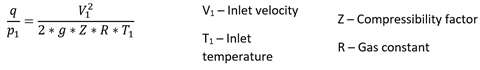
Elliott’s extensive factory test experience confirms the ASME straight run requirement and the velocity-static pressure ratio limit as adequate for test piping arrangements. Because velocity-static pressure ratios can be much lower than 0.01 in practice, the straight pipe requirements from the PTC have been modified, as listed in Table 1.
Table 1. Relationship between Velocity-Static Pressure Ratio and Straight Inlet Piping Length Recommendation
| q/p1 |
Straight Length (pipe diameters) |
|
0.005 |
1.5 |
| 0.01 | 3.0 |
| 0.015 | 4.5 |
Using the above values as benchmarks and solving the q/p1 equation, we can plot diameters of straight pipe run upstream of the compressor versus inlet velocity for various molecular weights (Figure 1).
Since most compressors have an inlet temperature range of 0°F to 100°F, the curve is based on 50°F. In this range, the built-in error is small. When the inlet temperature differs considerably, however, the straight pipe length can be determined with Figure 1 by correcting the actual inlet flow velocity to 50°F using the equation below for ideal gases.
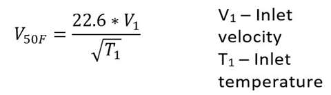
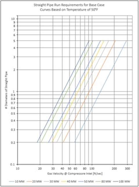 Figure 1. Relationship between Straight Pipe Length and Flow Velocity, depending on Gas Molecular Weight (MW)
The process detailed so far provides guidance on a basic starting point for the number of straight pipe diameters needed upstream of a compressor inlet.
This basic number will be modified with correction factors based on the components immediately upstream of the compressor. First, some common piping arrangements and correction factors need to be identified.
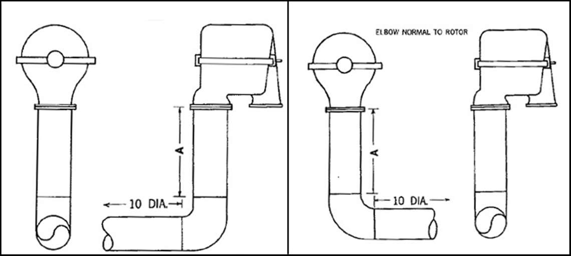
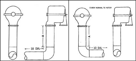 Figure 2. Orientation of Single Elbow Upstream of a Compressor [2]
For compressors, it is common for the inlet to be proceeded by a straight run of pipe downstream of a long radius pipe elbow. The elbow can be oriented with the pipe coming into the elbow parallel or normal to the compressor rotor, as shown in Figure 2.
When the upstream pipe is parallel to the compressor rotor, this arrangement is considered the least disruptive to the inlet flow, and the correction factor will be 1.
The upstream pipe being normal to the compressor rotor causes the gas volume entering the compressor to be greater on the side opposite to the direction from which the pipe approaches.
In other words, there will be a variation in axial flow across the pipe diameter. As a result, uniform gas distribution to the impeller is more difficult to obtain than for the base case, and the piping length recommendation should be multiplied by a correction factor of 1.5.
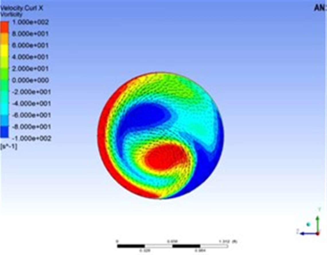
In regards to flow distortion, the single elbow results in the setup of a counter-rotating vortex pair, also called Dean Vortices, as shown in Figure 3.
Another common arrangement is two elbows immediately upstream of the inlet pipe, as shown in Figure 4. Again, there are two variations of this arrangement with the pipe (upstream of the elbows) oriented parallel or normal to the compressor rotor.
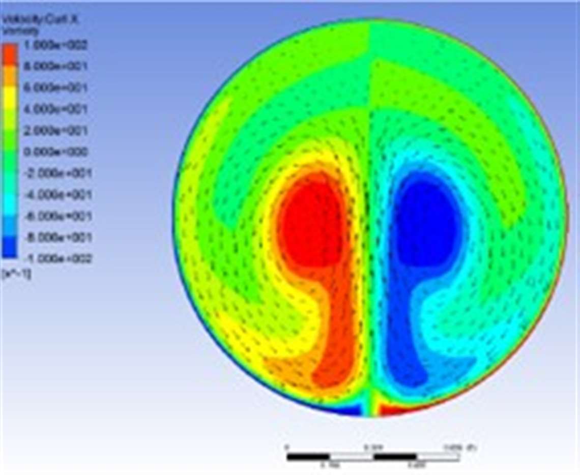
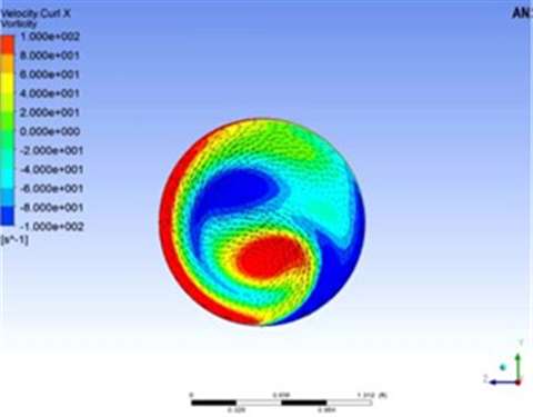 Figure 5. Downstream Vortices Produced by Two Out-of-plane Elbows [3]
When parallel to the compressor rotor, the gas flowing through these two elbows leaves the second elbow with a swirl or a rotating component, in addition to the normal velocity distortion associated with an elbow.
When normal to the rotor, this arrangement produces some swirl, but also the uneven distribution of flow outlined above.
For these reasons, the suggested correction factors for these two arrangements are 1.75 and 2, respectively. To illustrate the difference in flow distortion, Figure 5 shows the resulting vortices downstream of two elbows.
Compressors with axial inlets, typically single stage with overhung rotors, are more sensitive to upstream flow deviations because they do not typically have any inlet guide vanes. For this reason, a compressor with an axial inlet should have a 1.25 correction factor applied.
![Figure 4. Orientation of Two Elbows Upstream of a Compressor [2]](/Images/480xany/20220816-092604-Formula-6.jpg) Figure 4. Orientation of Two Elbows Upstream of a Compressor [2]
Figure 4. Orientation of Two Elbows Upstream of a Compressor [2]
If an axial inlet compressor has an elbow or two upstream of the inlet, the factors for parallel plane arrangements (Figure 4) would be used. Table 2 lists these correction factors as well as correction factors for other common arrangements.
Table 2. Piping Arrangement Correction Factors
| Arrangement | Correction Factor |
| One long radius elbow, plane parallel to rotor | 1.00 |
| One long radius elbow, plane normal to rotor | 1.50 |
| Two elbows, with second elbow plane parallel to rotor | 1.75 |
| Two elbows with second elbow plane normal to rotor | 2.00 |
| Butterfly valve before an elbow, valve axis normal to inlet | 1.50 |
| Butterfly valve before an elbow, valve axis parallel to inlet | 2.00 |
| Butterfly valve in straight run entering inlet, valve axis normal to rotor | 1.50 |
| Butterfly valve in straight run entering inlet, valve axis parallel to rotor | 2.00 |
| Two elbows in same plane, plane parallel to rotor | 1.15 |
| Two elbows in same plane, plane normal to rotor | 1.75 |
| Axial inlet | 1.25 |
To quantify how different upstream piping components, like valves, affect the straight run requirements, we can look at piping standards for performance testing as outlined in the PTC and requirements for uniform flow distribution (velocity profile) as applied to flow metering elements, published by both the ASME and the American Gas Association (AGA).
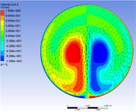 Figure 3. Dean Vortices from Single 90-degree elbow [3]
A velocity profile with minimum distortion is a critical requirement for a flow metering element such as an orifice or flow nozzle. Uniform velocity profiles are obtained by using long, straight runs of pipe and flow equalizers upstream of the metering element. The length of straight pipe is a function of the piping configuration preceding the straight run and the ratio of the orifice (or nozzle) diameter to the nominal pipe diameter.
This diameter ratio is referred to as the β-ratio. The requirements for flow metering accuracy are well established and generally recognized throughout the industry.
As the β-ratio increases, the length of straight pipe required for a given arrangement also increases. The reason for this is that as the orifice size increases for a given pipe diameter, a more uniform velocity distribution is required. Table 3 outlines the straight pipe run requirements for various piping components expressed in nominal pipe diameters for a β-ratio of 0.5 [4].
Table 3. Straight Pipe Run Requirements for Piping Components (β = 0.5)
| Piping Configuration | Straight Pipe Run Requirement (Diameters) |
| One Long Radius Elbow | 9 |
| Regulator or Partially Closed Valve | 25 |
| Gate Valve (open) | 6 |
| Check Valve | 11 |
Real world constraints can make it unrealistic to apply these requirements to the inlet of a compressor; however, the relationship of requirements for various configurations can provide valuable guidance for compressor inlet requirements.
For example, for a β-ratio of 0.5, one elbow requires 9 diameters, and a partially-closed valve requires 25 diameters. Therefore, the factor for one elbow (base case) is 9/9 or 1 and is 25/9 or 2.78 for a partially closed valve. If we look at the complete range of β-ratios, average the data, and let the single elbow be the base case, a series of correction factors can be developed.
Table 4 shows the correction factors developed based on the complete range of β-ratio data using a single elbow as the baseline [4].
Table 4. Piping Component Straight Pipe Run Correction Factors
| Piping Configuration | Correction Factor (F) |
| One Long Radius Elbow | 1.00 |
| Regulator or Partially Closed Valve | 3.00 |
| Gate Valve (open) | 1.00 |
| Check Valve | 1.25 |
To illustrate how this information can be applied, consider a hydrocarbon gas compressor with a molecular weight of 25, an inlet temperature of 85°F, and an inlet velocity of 100 fps. The piping arrangement is as shown in Figure 4 with the elbow plane parallel to the rotor, but in addition, there is a butterfly valve ahead of the two elbows.
Entering Figure 1 at 100 fps and a molecular weight of 25, a straight run of 1.45 pipe diameter is required. Applying the piping configuration correction factor of 1.75 and the butterfly valve factor of 1.5 gives: 1.45 x 1.75 x 1.5 = 3.8 diameters
Therefore, this arrangement requires approximately 4 diameters of straight pipe before the compressor inlet.
If a plant design cannot support the minimum straight run of pipes required by this method, a few options are available to reduce the requirements. The first would be to apply a special-mitered, vaned elbow as shown in Figure 4.
This elbow requires a minimum installation space, has a low loss factor, and provides for a minimum-of-velocity profile distortion downstream of the elbow. However, a poor velocity profile upstream is carried through the elbow. In addition, using two mitered, vaned elbows in series with one 90 degrees to the other will not create a swirl in the flow.
For large piping, the cost would be comparable to standard formed elbows. When mitered, vaned elbows are used in place of standard elbows, such as the one pictured, the correction factors may be divided by 2.
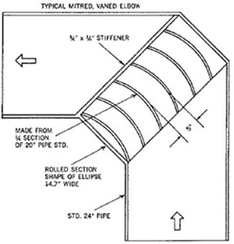 Figure 6. Mitered Vaned Elbow [5]
A second alternative to reduce straight pipe run requirements is a flow equalizer. The equalizer design should be in accordance with either ASME or AGA standards. These options can be expensive depending on the type used and will result in a horsepower penalty because there will be a significant pressure drop associated with them.
However, if the power penalty can be tolerated, a flow equalizer on the straight run into the compressor inlet may reduce the required straight length of pipe by a factor of 4.
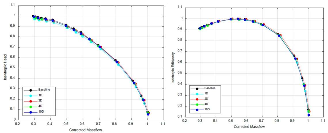
The inlet piping recommendations discussed previously are intended to reduce the effect of upstream piping features, such as elbows and control valves. However, there is little discussion on a practical method of confirming the effect before and after implementing the upstream piping changes. In Reference [3], the pipe length upstream of an axial-inlet centrifugal compressor had no significant effect on the compressor performance, as shown in Figure 7.
Recall that axial-inlet compressors are more sensitive to upstream pipe layouts. Therefore, it is likely that inlet piping has higher sensitivities to certain types of compressor designs, and this should be considered in applications before making significant modifications to the compressor installation.
This article originally featured in the COMPRESSORtech2 magazine.
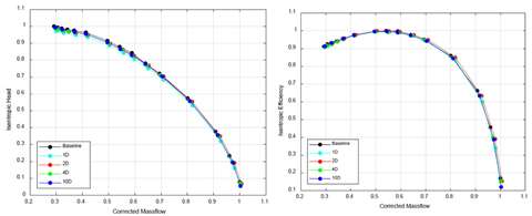 Figure 7. Upstream Pipe Length had no Significant Effect on Compressor Performance Downstream of a Single Elbow [3]
References
[1] 1997, Performance Test Code on Compressors and Exhausters, PTC 10 - 1997(R2014), American Society of Mechanical Engineers, New York.
[2] Hackel, R. A., and King, R. F. Jr., “Centrifugal Compressor Inlet Piping - A Practical Guide,” Compressed Air and Gas Institute, 4(2).
[3] White, B. A., Bueno, P. C., Fierro, F., and Cook, T. L., 2018, “Mechanical, Stress and Flow Considerations for Piping Design of Centrifugal Compressors,” Proceedings of the 47th Turbomachinery & 34th Pump Symposia, Houston, TX.
[4] 2004, Pressure Test Codes - Flow Measurement, ASME PTC 19.5-2004, American Society of Mechanical Engineers.
[5] 1962, Aerospace Applied Thermodynamics Manual, SAE International.
MAGAZINE
NEWSLETTER


CONNECT WITH THE TEAM


![Figure 4. Orientation of Two Elbows Upstream of a Compressor [2]](/Images/1140xany/20220816-092604-Formula-6.jpg)