
Giving a second life to a refurbished centrifugal compressor
March 07, 2022
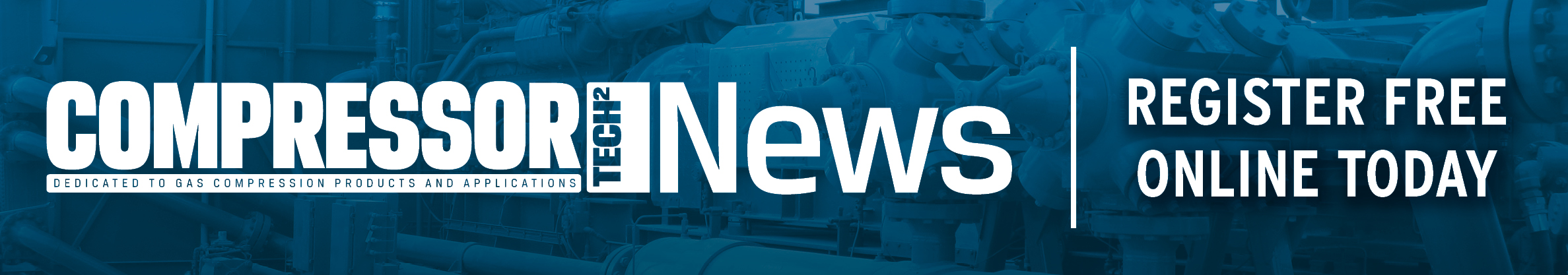
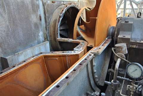 Figure 1 – Blower case open. 3D semi-open impeller visible
During centrifugal compressors life, end users and service companies often experience performance reduction as well as component deterioration/malfunction or even have to face the need to rerate the machine on new requested operating conditions. Obviously, whenever possible, it is fundamental to prevent a useless, costly, and time-consuming machine replacement. Thus, it is crucial to exploit the ever-increasing opportunities available in refurbishing/rerating old centrifugal compressor to give them a second efficient life.
Several innovative technologies developed in the last decades allow to carry out refurbishing activities that were not feasible some time ago. Newer manufacturing technologies together with the development of innovative materials with improved mechanical properties allow nowadays to keep pushing beyond the previous technical limits for industrial application. Moreover, the recent advanced tools for geometry acquisition (e.g. 3D scan) enable to investigate possible damages, defects and other geometrical details that would not be detected otherwise. Eventually, the increasing accuracy and reliability of modern simulation tools, such as CFD, FEA and rotor-dynamic (lateral and torsional) analyses, let to perform more accurate investigations of the physical phenomena causing the issues that may be experienced.
The main aim of this paper is to spread knowledge of such innovations and let end users, service companies and all people involved in industrial process plants to be aware of some of the countless opportunities that the new technologies have created in the field of centrifugal compressors service and upgrades. Among the several refurbishing/rerating activities carried out by Compression Service Technology–CST in the last years on turbomachinery, two case histories are described in this paper, showing how problems of different nature can be successfully solved to improve the effectiveness even of very old machines.
Case 1: Restoration of erosion damages on impeller
A combustion air blower of a sulfuric acid production plant, driven by electric motor and controlled by Inlet Guide Vane (IGV), intakes air at atmospheric conditions and delivers it at 1.4 bara discharge pressure; the requested air mass flow rate is about 200.000 kg/h while shaft power is about 2.6 MW. As shown in Figure 1, the compressor is single stage overhung impeller, composed of a welded-type 3D semi-open impeller (external diameter 1600 mm) having a connection ring at blades tip on inlet section, a short vaneless diffuser, and a welded-type volute with rectangular cross section.
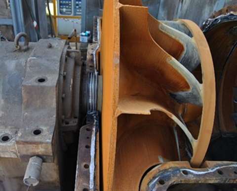 Figure 1 – Blower case open. 3D semi-open impeller visible.
During its lifetime, the end user experienced a progressive decrement of compressor performance, both in terms of delivered flow rate and efficiency, until he decided to refurbish it to recover its original performance. CST was involved in such activity by the Service provider in charge of the combustion air blower maintenance.
A 3D laser scanning was performed to obtain compressor 3D model for investigation. As shown in Figure 2, high clearance was detected by the impeller scan. High gap, enhanced by erosion, between impeller blades tip and stator shroud was observed: its magnitude was found variable along the blade length from 3.5‰ to 8‰ of the impeller diameter, instead of the usual expected range of 1-2‰. Moreover, the gap between impeller blades ring and the relevant static slot was found quite large.
A CFD analysis was carried out to verify the fluid dynamic behavior of the damaged compressor, focusing on how much the compressor performance might be affected by the high tip gap clearance mentioned above. As shown in Figure 3, the presence of excessive clearance leads to a non-optimal flow-field. Two main fluid-dynamic phenomena, affecting negatively the optimal flow, were identified:
- a remarkable backflow around impeller blade ring
- a significant tip blade parasitic leakage flow (5.7% of impeller inlet flowrate)
These anomalies were considered as the main causes of the reduced stage efficiency and delivery flow rate.
 Figure 2 - Impeller/shroud cross section with obtained impeller clearances.
The possible presence of a labyrinth seal in the original compressor configuration was inferred, given the high gap found between impeller blades ring and the statoric slot. That seal could be gone loose by erosion or other occurrences during compressor operation. Unfortunately, no information confirming such assumption was found from available documents and drawings.
In order to restore a good compressor performance and, at the same time, avoid a too long time for installation and consequent facility extended downtime, the following two-step solution in sequence was implemented, leveraging a deep theoretical CFD investigation:
- the insertion of a labyrinth seal into the static slot, corresponding to the impeller inlet ring;
- the welding of an overlay on the impeller blades tip, to get an evenly reduced gap with the statoric part.
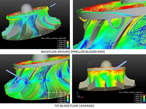 Figure 3 - CFD results: flow field visualization.
The CFD investigation campaign was carried out with the progressive implementation of that “two-step” sequence. The CFD investigation highlighted the importance of the reduction of the gap between the rotating and static components. The clearance between the impeller blades tip and the stator shroud came out to be of utmost importance for the performance recovery.
Eventually, the concurrent presence of the labyrinth seal into the static slot on the impeller inlet ring and a blade tip clearance reduction of about 50% with respect to the measured ones was investigated to find the final impeller configuration. The result was that, by the modifications introduced, an increase of +1% of the compressor efficiency and of +6% of delivered flow rate could be got, thus achieving a satisfactory recovery of the combustion air blower performance.
The corrective actions defined by the above investigation were successfully implemented in the field and the customer experienced a performance recovery consistent with the forecasts of the CFD analysis.
Case 2: Compressor performance recover by impeller renewal
During a routine overhaul of a 6 stages horizontally split air centrifugal compressor, the service company discovered the presence of strong erosion damages on the last impeller and asked CST to find a solution to this problem. The original closed impeller had been manufactured by an old manufacturing technology, using rivets to fix the blades to the disc and shroud (see Figure 4).
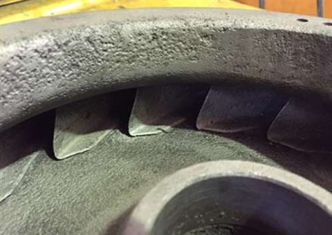 Figure 4 – Original last compressor impeller (as found during standard overhaul.)
It was decided to substitute the impeller with a new one having the same meridional channel and blade camber profile to restore compressor performance. Since the original construction drawings and material specification were not available, some 3D scan of geometry measurements and chemical analysis were performed.
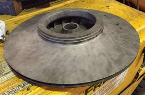 Figure 4 – Original last compressor impeller (as found during standard overhaul.)
ASTM A705 Gr.630 (17-4 PH) was used instead of the original carbon steel, thus improving the resistance to corrosion and erosion and avoiding the occurrence of the experienced erosion damages. Moreover, the single-piece EDM manufacturing technology was adopted for the new impeller, obtaining a better blade profile with the following advantages:
- leading edge with a properly defined radius
- smoother flow path with a higher repetition accuracy among the various impeller channels
- avoidance of defects and obstructions due to the set up method adopted in the original impeller (rivets, see Figure 4.)
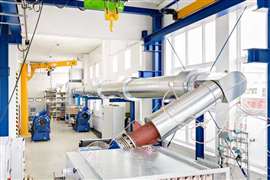
New manufacturing drawings and specifications were produced, including balancing and overspeed test instructions. Figure 5 shows the new impeller during EDM manufacturing.
The new impeller was mounted on the new rotor and installed in the existing compressor with full satisfaction of the customer. In fact, in addition to the erosion damages restoration, a higher performance of the compressor was achieved due to the higher efficiency of the refurbished stage (about +2%).
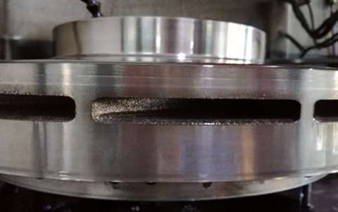 Figure 5 – New compressor impeller during single-piece EDM manufacturing.
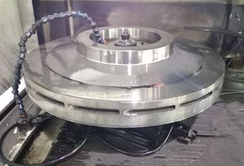 Figure 5 – New compressor impeller during single-piece EDM manufacturing.
********
Above examples show that old units, even if they have been operating for many decades and had several recurrent failures, once revamped, can continue to work efficiently and with improved performance. Refurbishment actions can be carried out to solve issues related to machine aging, erosion, and wear, to restore original performance or improve them. Furthermore, centrifugal compressors can be revamped and rerated to meet new plant operating conditions.
Service companies and end-users dealing with the “repair or replace” trade-off should be aware of the countless refurbishing opportunities that are nowadays available on turbomachinery, thanks to the several innovative technologies developed in the last decades. New advanced manufacturing technologies, innovative materials, availability of new equipment for geometry acquisition and, last but not least, great accuracy of modern tools for fluid-dynamic and mechanical analyses, can significantly help to give a more efficient second life to old centrifugal compressors.
Authors: Andrea Fusi*, Andrea Betti*, Emanuele Burberi*
*C.S.T. Compression Service Technology Srl
MAGAZINE
NEWSLETTER


CONNECT WITH THE TEAM