

VFDs – The torsional analyst’s best friend or worst enemy? Part 4
July 04, 2022
This paper was first presented at the Gas Machinery Research Council 2021 Gas Machinery Conference in Louisville, Kentucky in October 2021. Because of the original length of the paper, it has been divided into four parts. The final segment is published here.
The third primary control type is Direct Torque Control (DTC), which is also a closed loop control system. This is a type of control known as hysteresis or “bang-bang” control. In hysteresis control, a narrow band is placed around the desired value of the regulated variable.
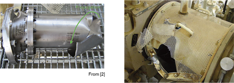 Figure 1 – Sample VFD Torsional Failure (Courtesy of Kocur and Corcoran [26])
As long as that parameter is within the designated band, no action is taken. But, as soon as the parameter strays outside of that band, the control system jumps into action to return it to its desired value.
In DTC, there are actually two controlled parameters – stator flux and motor torque. Thus, this control system has two hysteresis bands – one for flux and the other for torque. Like vector control, this system also employs a motor model and is closed loop, in that both the phase currents and voltages are measured.
Unlike vector control, the large majority of DTC systems operate without any measurement of rotor speed or position. Since DTC also controls the voltage vectors being fed to the motor, it is technically a form of vector control.
Both vector control and DTC provide much better dynamic performance than does scalar control. If it is desired to use the control system to damp out torsional vibration (which has been successfully accomplished), one of these two systems must be used – scalar control is not an option. Although the various providers of these systems claim that their system provides the best dynamic performance, Holopainen, et. al. [19] state that the two systems provide fairly equivalent dynamic characteristics.
Regardless of which type of control system is employed, a key characteristic of it is its torque control bandwidth. A control’s bandwidth, which is given in Hz, is the max frequency that a control can accurately “follow” changes in the desired torque. Bandwidth is essentially a measure of the control’s responsiveness, with a higher value being better.
It is common practice to define the bandwidth as the highest frequency at which the response decreases by less than 3 dB. For modern systems, the bandwidth typically falls between 20 and 200 Hz. The lower extremes are usually associated with LCIs while the higher numbers can only be achieved with VSIs using vector control or DTC.
Now that the reader is acquainted with some of the control system basics, we can address the main point of this section – control instability. Rotondo, et. al. [31] describe the instability mechanism as follows. Torsional vibration in the drive train results in an oscillation in train speed.
If the torsional mode that is excited is active in the motor core region, there is an accompanying variation in motor speed. This variation is seen by the electrical system as a fluctuation in counter electromotive force (EMF) within the motor. The EMF variation is followed by a pulsation in the motor current.
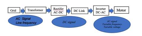 Figure 2 – VFD Block Diagram
Since motor torque is proportional to current, a torque oscillation follows, and this is seen by the control system as a disturbance in the torque control loop. What happens next depends on the dynamics of the entire system. The disturbance can be attenuated or it can be amplified. If the latter, a mechanical failure within the train can result.
Since this phenomenon almost always occurs at one of the train’s torsional natural frequencies (usually the first), the behavior of the control at these frequencies is critical. Some control systems will dissipate energy at those frequencies, leading to a stable system. On the other hand, some units will add energy at one or more of those frequencies, potentially creating instability and mechanical failures in the train components.
Del Puglia, et. al. [10] point out that this is where the concept of bandwidth can be a double-edged sword. Although most think a control having a larger bandwidth is better, that does not come without a price. As they point out, any natural frequencies that are within the torque control bandwidth are candidates for instability. Thus, the larger the bandwidth, the more torsional modes that need to be worried about. This is not a great concern, nevertheless, since instability almost always involves the first two torsional modes, primarily the first.
Although the majority of the controls discussion has involved VSIs, that is not to imply that instability problems only occur with drives of the VSI type. On the contrary, Del Puglia, et. al. [10] give an example where an instability in a CSI led to unacceptable torsional vibrations. Since the mode that went unstable was the second, this is one case in which the instability did not involve the first mode.
On the flip side, along with creating torsional problems via instability, VFD control systems can also be used to provide electrical damping to damp out torsional modes (once again, usually the first mode). This concept, which also requires a sophisticated E/M simulation to design, has been proven out by a number of researchers, including Maragioglio, et. al. [28], Sihler, et. al. [33], Sihler, et. al. [34], and Bruha and Peroutka [6]. In general, in order for a control to be effective at damping out a torsional mode, its bandwidth must be at least twice the natural frequency of the mode in question.
Usually, the damping can be done by tuning the speed controller properly. Myszynski and Deskur [30] provide rules for tuning the commonly used PID (proportional plus integral plus derivative) speed controller to damp resonances in a three moment of inertia mechanical system. Of course, the use of the control system to damp out torsional modes, while undeniably achievable, is far more the exception than the rule for field units.
The bottom line of this section is the reader should at least be aware that control instability can cause torsional failures when there is a VFD in the system. Unfortunately, there is not much that can normally be done to predict/prevent it in the design phase. However, it is useful to keep in mind that such problems are more likely to occur with vector control or DTC than with simple scalar control.
Additionally, Holopainen, et. al. [19] provide the following best practices for avoiding this destructive phenomenon:
- Tune the process control so that it is slower than the speed control
- Tune the speed control so that it is slower than the torque (or current) control. This is particularly critical when dealing with large LNG trains.
- Consider using the VFD in torque-controlled mode only, by integrating the speed control directly into the process control.
Practical methods for dealing with VFDs
In a perfect world, performing a torsional analysis on a system being driven by a VFD would be fairly straightforward. The VFD supplier would supply the analyst with all the excitation amplitudes and frequencies that the VFD generates and the analyst would then use them in a conventional torsional analysis, as outlined herein.
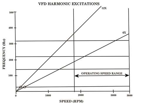 Figure 7 - Campbell diagram showing VFD harmonic excitations
But, in the author’s experience, the scenario described above occurs in a very small fraction of real world situations. De la Roche and Howes [9] confirm that they have had similar experiences, as they state that, “Two different VFD manufacturers in these cases were reluctant to admit that mechanical vibration problems can be caused by the electrical side of the system. This experience suggests that most VFD manufacturers will behave the same way.”
The realities are as follows:
- When queried for the harmonic and inter-harmonic excitations generated by their drive, many VFD suppliers will claim that they are insignificant. However, real world experience suggests that such claims can be overly optimistic, for two reasons. First, in many cases, the actual amplitudes in the field are significantly greater than what had been predicted. Second, as is noted by Sihler, et. al. [34] and Song-Manguelle, et. al. [37], especially when the excitations in question are inter-harmonics, even excitations less than 1.0% of motor rated torque (the level below which most VFD suppliers consider the excitations to be insignificant) can create problems. Reference [37] states that excitations as low as 0.65% of rated torque can generate issues and some of the failures described in the other references occurred with excitations smaller than that.
- Another typical claim of VFD suppliers is, “Harmonics are not an issue because we have a filter between the inverter and the motor.” While there are undoubtedly some filters that can be helpful, experience has made the author dubious of this claim, too. Many of the documented failures occurred with filters in the line. In the author’s experience, the presence of a filter means little.
- Other VFD suppliers will simply refuse to provide the excitations needed for the torsional analysis. They will either admit that they are incapable of calculating them, or will claim that the information is proprietary.
- Some VFD suppliers will provide test data from a VFD-motor combination that is similar to, but not the same as, the one under consideration. However, as is pointed out by Hudson [21], the excitations are a function of the combination of the drive and motor. Thus, unless the test is run with the actual drive, motor, and control system under consideration, the test data is not usable.
- When asked for “harmonic data,” many VFD suppliers will provide data on input or output current harmonics. This is of little use to the analyst, who needs torque harmonic data in order to perform the analysis.
- The VFD supplier will sometimes provide torque harmonic data for only one operating condition, usually the rated condition. This can be misleading since the excitation magnitudes can vary greatly as the operating speed is varied, especially if the drive is of the CSI/LCI type.
- If the VFD supplier provides any excitation data at all, it will almost always be for the harmonic excitations only. Inter-harmonic excitation data is very difficult to obtain. In all the time he has been doing this, the author can only recall two occasions when inter-harmonic data was provided. And, on both occasions, the data was quite vague.
Thus, analysts will often find themselves “on their own,” especially with respect to the inter-harmonic excitations. In this common situation, although the analyst might be tempted to ignore all inter-harmonic excitations, that approach can be risky. Instead, it is recommended that the analyst perform a “bounding analysis,” as follows:
- If the drive is a CSI or an LCI, assume the inter-harmonic excitations are given by Equation [4] and that the amplitude is 3.0% of motor rated torque.
- If the drive is a VSI, the excitation frequencies are too nebulous to even try and guess at what they would be. Instead, the analyst should assume the worst case condition, where the inter-harmonic excitation generates a resonance with the first torsional mode right at MCOS. The excitation amplitude should be taken to be 1.0% of motor rated torque.
Using the above assumptions, the analyst should analyze the train in the usual manner. If the train is capable of handling the assumed conditions, then it can be considered capable of handling inter-harmonics. If not, then the assumed situation should be presented to the VFD supplier and assurances sought that the analyzed condition will not actually occur in the field.
It should be noted that the 3.0% and 1.0% values given above only apply to drives produced by “reputable suppliers” (i.e., the well-known names in the field). If the drive was supplied by some fly-by-night operation, the inter-harmonic excitations could very well be higher than those values. The author is currently working on a project where that is precisely what happened.
The author is not alone in using this approach as Ganesan, et. al. [16] recommend a similar procedure. They state, “If intersections of the torsional modes with LCI drive excitation frequencies are identified, the following investigations may give a clear picture – check the drive train integrity by using a drive supplier independent worst case value of 2% for the excitations. #
This can be performed by the OEMs without any input from drive suppliers for the LCI drive. If the drive train integrity is intact with the worst case excitation magnitudes (indicative value of 2% independent of the interharmonic frequency), then the risks of failures due to torsional problems are very low. If the stress levels on the drive train components are higher than the threshold limits for worst case excitation magnitudes, detailed analysis should be performed by the drive suppliers and the OEMs. The drive suppliers should calculate the project specific air-gap interharmonic torque excitations.”
Thus, with that clarified, when there is a VFD in the system, the following courses of action are recommended:
- Per Kocur and Muench [27], purchase specifications for trains incorporating VFDs should specify upper limits on the torque modulations from harmonic, inter-harmonic, and white noise produced by the VFD electrical systems. This is something that is done far too infrequently right now.
- The analyst should account for harmonic excitations using the information obtained from the drive supplier.
- Unless the supplier provides information on the inter-harmonic excitations, the analyst should use the conservative procedure provided herein to account for them.
- If an LCI is included, a transient start-up analysis might be needed.
- If there is a condition in which the electrical frequency feeding the motor can be within 10% of the first torsional mode, analyses should be performed for line-to-line and three-phase short circuits.
- In all cases, good communication between the VFD supplier, motor supplier, driven component supplier, end user, and torsional analyst is paramount.
Conclusion
In this paper, VFDs have been described and the manner in which they complicate a torsional analysis has been explained. The biggest issue VFDs introduce is they often generate torsional excitations that have amplitudes and/or frequencies that were unexpected during the design phase. A method that the author has used for years to get around these limitations is provided in the hope that users will utilize it to avoid running into field problems.
Although a lot of ground has been covered, the primary points that the reader should remember are as follows:
- When there is a VFD in the system, excitations from the VFD are often dangerous and need to be included in the torsional analysis.
- Although the amplitudes of VFD inter-harmonic excitations are usually smaller than those of their harmonic counterparts, they are usually more the more dangerous of the two.
- The idea that the CSI/LCI architecture is more dangerous from a torsional standpoint is a myth. VSIs are at least as lethal, and, in the author’s opinion, they are more so.
- The idea that short circuit analyses do not need to be performed if there is a VFD in the system is also a myth. VFD-driven trains need to be analyzed in a similar manner to fixed speed trains.
- If the VFD supplier does not provide all of the needed technical data, there are methods (given herein) for getting around that.
- Most importantly, assistance from the VFD supplier will usually be limited or nonexistent. The mechanical engineer is usually “on their own.”
Part one is available here
Part two is available here
Part three is available here
The author
 Mark A. Corbro, P.E. is the president and chief engineer of No Bull Engineering (Photo: Mark A. Corbro)
Mark A. Corbo, P.E. is the president and chief engineer of No Bull Engineering, a high technology engineering/consulting firm located in Bradenton, Florida. In this position, he provides rotordynamics and torsional vibration analyses to various clients in the compressor industry. Corbo has B.S. and M.S. degrees (Mechanical Engineering) from RPI. He is currently serving as the Torsional Vibration Chair on the API 684 Rotordynamics Task Force. His week-long training course, “Practical Rotordynamics for Real Machinery,” which he collaborates on with two other consultants, is considered by many to be the finest in the world.
References
[4] API Standard Paragraphs Rotordynamic Tutorial: Lateral Critical Speeds, Unbalance Response, Stability, Train Torsionals, and Rotor Balancing, API Technical Report 684-1, First Edition (November 2019).
[6] Bruha, M. and Peroutka, Z., “Torsional Vibration in Large Variable Speed Drive Systems: Origin and Mitigation Methods,” Proceedings of the 17th European Conference on Power Electronics and Applications, IEEE (September 2015).
[9] De La Roche, L. and Howes, B., “Lateral and Torsional Vibration Problems in Systems Equipped with Variable Frequency Drives,” Proceedings of GMRC (2005).
[10] Del Puglia, S., De Franciscis, S., Van de moortel, S., Joerg, P., Hattenbach, T., Sgro, D., Antonelli, L., and Falomi, S., “Torsional Interaction Optimization in a LNG Train With a Load Commutated Inverter,” Proceedings of the Eighth IFToMM International Conference on Rotor Dynamics, KIST, Seoul, South Korea, pp. 994-1001 (September 2010).
[16] Ganesan, V., Beuermann, M., Kalbfleisch, P., and Hilscher, M., “Electrical Damping of VFD Induced Torsional Torque Pulsations in a LCI Driven Compressor Drive Train,” Proceedings of the Forty-Sixth Turbomachinery Symposium, Turbomachinery Laboratory, Texas A&M University, College Station, TX (December 2017).
[19] Holopainen, T. P., Niiranen, J., Joerg, P., and Andreo, D., “Electric Motors and Drives in Torsional Vibration Analysis and Design,” Proceedings of the Forty-Second Turbomachinery Symposium, Turbomachinery Laboratory, Texas A&M University, College Station, TX (October 2013).
[21] Hudson, J. H., “Selection, Design and Field Testing of a 10,500 HP Variable Speed Induction Motor Compressor Drive,” Proceedings of the Twenty-Fifth Turbomachinery Symposium, Turbomachinery Laboratory, Texas A&M University, pp. 25-34 (September 1996).
[26] Kocur, J. A. and Corcoran, J. P., “VFD Induced Coupling Failure,” Case Study Presented at the Thirty-Seventh Turbomachinery Symposium, Turbomachinery Laboratory, Texas A&M University, College Station, TX (2008).
[27] Kocur, J. A. and Muench, M. G., “Impact of Electrical Noise on the Torsional Response of VFD Compressor Trains,” Proceedings of the First Middle East Turbomachinery Symposium, Turbomachinery Laboratory, Texas A&M University, Doha, Qatar (February 2011).
[28] Maragioglio, G., Sgro, D., Calore, P., Failla, L., and Tenca, P., “Torsional Modal Damping of a LCI Driven Geared Motor-Compressor Train: Evaluation, Optimization Criteria, and Active Control,” Proceedings of the Forty-Sixth Turbomachinery Symposium, Turbomachinery Laboratory, Texas A&M University, College Station, TX (December 2017).
[30] Myszynski, R. and Deskur, J., “Damping of Torsional Vibrations in High-Dynamic Industrial Drives,” IEEE Transactions on Industrial Electronics, Vol. 57, No. 2, pp. 544-552 (February 2010).
[31] Rotondo, P., Andreo, D., Falomi, S., Joerg, P., Lenzi, A., Hattenbach, T., Fioravanti, D., and De Franciscis, S., “Combined Torsional and Electromechanical Analysis of an LNG Compression Train With Variable Speed Drive System,” Proceedings of the Thirty-Eighth Turbomachinery Symposium, Turbomachinery Laboratory, Texas A&M University, College Station, TX, pp. 93-101 (September 2009).
[33] Sihler, C., Schramm, S., Rossi, V., Lenzi, A., and Depau, V., “Electronic Torsional Vibration Elimination for Synchronous Motor Driven Turbomachinery,” Proceedings of ASME Turbo Expo 2011, ASME, Vancouver, BC (June 2011).
[37] Song-Manguelle, J., Schroeder, S., Geyer, T., Ekemb, G., and Nyobe-Yome, J. M., “Prediction of Mechanical Shaft Failures Due to Pulsating Torques of Variable Frequency Drives,” IEEE Transactions on Industry Applications, Volume 46, Number 5, pp. 1979-1988 (September/October 2010).
MAGAZINE
NEWSLETTER


CONNECT WITH THE TEAM