

VFDs – The torsional analyst’s best friend or worst enemy?
March 10, 2022
Note: This paper was first presented at the Gas Machinery Research Council 2021 Gas Machinery Conference in Louisville, Kentucky in October 2021. Because of the original length of the paper, it has been divided into multiple parts. The first part, published here, includes an abstract, introduction, problems created by VFDs and VFD fundamentals.
Abstract
In both rotating and reciprocating machinery, electric motor-driven trains suffer more torsional vibration problems than those driven by turbines or engines. The problem is compounded if the motor is driven by a variable frequency drive (VFD). In the author’s experience, VFDs have been creating torsional failures at an alarming rate over the past two decades. Even more alarming is the fact that the torsional analysis was performed properly for almost all of those cases. Issues ultimately arose because the VFD behaved in unanticipated ways in the field.
The paper begins with a brief review of some of the many VFD-driven failures that have been reported over the last two decades. It then delves into a description of the major components inside a VFD, and how they work. Since the author realizes that, like himself, most of his audience are not electrical engineers, this portion is written from a practical, big picture standpoint. It is not important that compressor design engineers, packagers, and end users understand the minutiae of how VFDs work, but it IS important that they have a general grasp of the fundamental concepts.
Keeping with the practical orientation of the paper, the four ways in which the presence of a VFD complicates a torsional analysis are described in detail. It is the author’s experience that a preponderance of engineers are only aware of the first – the fact that the presence of a VFD (and the accompanying wide speed range) makes achievement of the required separation margins much more difficult. However, it is also the author’s experience that the second, the fact that the VFD, itself, introduces torsional excitations into the system, is often the most heinous. Particular focus is placed on the harmonic and inter-harmonic excitations that are unique to VFDs, and which are vastly different for the two major architectures (current source inverters and voltage source inverters). The third and fourth factors, namely increased likelihood of resonance in the event of a short circuit and instabilities in the VFD’s control circuit, are also examined.
This leads to the most important part of the paper – how to deal with these issues in the design stage. Engineers are always encouraged to get as much information from the VFD supplier as possible, and in an ideal world they get everything needed. However, unfortunately, in the vast majority of situations, this information is either incomplete or totally unavailable. Accordingly, the paper provides practical guidelines for steps to take when the needed information is not all there to ensure a train will not suffer any VFD-related field failures.
INTRODUCTION
Torsional vibration is a subject that should be of concern to all rotating and reciprocating equipment users. Since torsional behaviour is seldom monitored in the field, performance of a thorough torsional analysis during the design phase is imperative. A comprehensive procedure for doing so is provided in Corbo and Malanoski [8].
In the world of rotary and reciprocating compressors, torsional problems occur more frequently when the compressor is driven by an electric motor instead of a turbine or engine. Moreover, the chances of failure escalate even more when the motor is controlled by a variable frequency drive (VFD). Not only does the failure probability increase, the presence of a VFD also substantially increases the complexity of the torsional analysis.
There are four primary reasons for this:
- The larger operating speed range makes it much more difficult to demonstrate the required 10% separation margin for all interference points, as compared to a fixed speed system. Since almost all engineers seem to understand this, there is no need to elaborate herein.
- Excitations from the VFD need to be considered in the analysis, as they are a potential cause of torsional failures.
- The variation of the electrical frequency being fed to the motor makes it more likely that a short circuit condition can trigger a resonance with the first torsional mode.
- The VFD’s control system can go unstable at the frequency of a torsional mode, leading to failures in the mechanical train.
It is the author’s experience that although most mechanical engineers fully grasp the first item, many are completely unaware of the other three. Accordingly, the focus herein is on those three aspects.
In addition to the complexity, the criticality of the torsional analysis also increases when a VFD is in the system. This is because there has been a slew of VFD-driven torsional failures reported over the last 20 years or so, a sampling of which are described herein. And, in the majority of the cases the author has studied, a torsional analysis was performed during the design phase. And, as far as the author can tell, the analysis was conducted properly, considering the information available to the analyst at the time. The problems arose because the VFD behaved in an unanticipated manner when it got into the field. Either it generated excitation frequencies that were not expected at all, or it brought about excitations that were much larger than were anticipated.
The fact that there has been a rash of VFD-driven torsional failures in the last two decades does not by any means imply that such problems were unknown previously. Case studies involving failures driven by “old-style” VFDs are provided in [20], [21], and [42]. However, there is one enormous difference between the two classes of failures. While the “old-time” failures are well-understood, many of the more recent ones are not. This places the mechanical engineers that have to design, analyze, and ultimately use these trains in a conundrum.
In response to this outbreak of problems, the VFD suppliers are doing next to nothing. Many claim to not be aware of the problems. Others acknowledge that other manufacturers’ products have experienced issues, but deny having ever seen it in any of their units. Even worse, the VFD supplier will sometimes deny that their drive is causing a problem even when confronted with test data that shows otherwise. The author has direct experience with this. The message to the reader is this – expect little to no assistance from the VFD supplier.
The onus for solving this problem is, thus, thrust squarely upon the mechanical engineers responsible for the integrity of the train. The author’s procedure for handling this is the main topic of this paper.
PROBLEMS CREATED BY VFDS
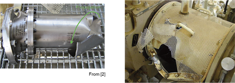 Figure 1 – Sample VFD Torsional Failure (Courtesy of Kocur and Corcoran [26])
Before examining the workings of VFDs, a discussion of why they are of such concern is warranted. Examples where VFDs have created problems follow, although this list is not intended to be all-inclusive.
Tsukakoshi, et. al. [43] and Kocur and Corcoran [26] describe a problem they experienced with a centrifugal LNG compressor train containing a gearbox. The train was driven by a 13.65 MW induction motor controlled by a VFD employing pulse width modulation (PWM). They found that the speed feedback showed continuous vibration with a measured frequency of 14 Hz, which was the first torsional frequency of the system. Torsional-to-lateral coupling at the gear mesh also generated measurable lateral vibrations in the gearbox. As a result of the torsional vibration, the LP compressor coupling failed spectacularly (as is shown in Figure 1 taken from Kocur and Corcoran [26]) after 2000 hours of operation. The problem was ultimately attributed to inter-harmonics arising from the VFD exciting the first torsional mode and was rectified by modifying the VFD and its control system.
Kocur and Muench [27] give two case studies where VFDs created torsional problems in compressor trains. In the first train, inter-harmonics and signal feedback led to a failure of the pinion-to-LP compressor coupling. In the second train, excessive gear vibrations were noted at a frequency corresponding to the first torsional mode. Whereas the VFD was again confirmed to be the source of the vibration, unlike the first case, there were no discrete frequencies being generated by the VFD. Instead, the high vibrations were attributed to white noise from the VFD exciting the first torsional mode.
Adachi, et. al. [1] describe a high lateral vibration problem caused by torque oscillations in a geared centrifugal compressor train. Once again, the VFD was identified as the excitation source. Inter-harmonic excitations from the VFD were resonating with the first torsional mode, and torsional-to-lateral coupling at the gear mesh was converting the torsional vibration into large lateral motions in the gear shafts. The most troubling aspect of this problem is the frequencies that were observed to be participating in the inter-harmonics were not the frequencies that would have been predicted by conventional methods.
Baccani, et. al. [5] report on a geared train where VFD-induced torsional vibrations at the train’s first torsional mode of 9 Hz were converted to radial vibrations via torsional-to-lateral coupling. Amplitudes in excess of 150 microns (0.006 in.) were observed to occur at that same frequency.
Alexander, et. al. [3] describe issues that occurred in a train consisting of a 952 hp induction motor driving a mechanical vapor recompressor (MVR) fan through an elastomer-in-compression (aka Holset) coupling. The train suffered torsional failures in both the coupling and fan. In fact, the fan torsional vibration was so excessive that the fan wheel threw a blade and the resulting excessive unbalance sent the lateral vibrations through the roof, triggering an automatic shutdown. While both failures were ultimately attributed to excitations coming from the VFD, the aspect that the author finds most intriguing is that while the coupling failure involved the first torsional mode, the fan blade failure was due to a resonance with the second mode. The problems were finally eliminated by switching the VFD control algorithm from sensorless vector to scalar control.
Eshleman [12] details motor shaft failures that were experienced in three out of four identical 300 hp vertical pumps driven by induction motors. Extensive testing revealed that a 5X excitation having an amplitude of 13.9% of the motor’s rated torque was driving a resonance with the first torsional mode, thereby causing the shafts to fail. There are two curious items here. First, as will be seen later, a 5X excitation is not a normal excitation put out by typical VFDs. Second, as will also be seen later, that is a high excitation magnitude. Unfortunately, the reference, a fairly short magazine article, does not contain enough detail for the reader to figure out what was going on. This problem was ultimately solved by changing to an elastomer-in-compression coupling to lower the first natural frequency and add damping to the train.
Feese and Maxfield [14], discuss a case where the oscillating torque in a motor/induced draft fan train was observed to be excessive whenever the VFD was operated at an electrical frequency above the first torsional natural frequency. They were not dealing with a resonance condition since, once the electrical frequency exceeded the first torsional mode, the oscillating torques never dropped, regardless of how far above the first mode they went. Indeed, the phenomenon seemed much more like a classical lateral rotordynamics instability than a typical torsional problem. Although they finally arrived at an adequate design by making changes to the system, it is not clear if they ever fully understood why the excessive torques were occurring.
De la Roche and Howes [9] describe a case that is remarkably similar to that depicted by Feese and Maxfield [14], although the two trains were significantly different. Their system consisted of a four-throw reciprocating compressor driven by an induction motor, with a flexible coupling and isolating flywheel between them. This train suffered several motor shaft failures in the stub shaft area caused by torsional vibration. Measurements revealed that as the speed was increased and the first torsional mode was excited, the torsional vibrations peaked and then the amplitude of the torsional vibration stayed high at the TNF even though the motor speed was still increasing. In other words, they observed the exact same eccentric behavior as did Feese and Maxfield. The problem was eventually solved by making changes to the VFD’s control settings, but De la Roche and Howes make it clear that the VFD supplier did not share what those changes were with them. Unfortunately, this is all-too-often the case.
Once again, this list is hardly meant to be all-inclusive. For instance, the VFD-related problems that the author has worked on have never been published because of the unwillingness of one or more of the parties involved to make those issues public. However, it is the author’s hope that the gravity of the situation is now apparent to the reader.
VFD FUNDAMENTALS
Although the large majority of readers of this work are mechanical engineers, it is necessary to understand some of the electrical engineering basics of VFDs in order to perform a competent torsional analysis when one is present. One of the biggest stumbling blocks to doing that is often a communication gap between the electrical engineers designing the VFD and the mechanical engineers performing the torsional analysis. Accordingly, the better the analyst understands the electrical workings of the VFD, the greater the likelihood of a good analysis being performed.
VFDs are used to allow prime movers (i.e., compressors, fans, or pumps) to run at variable speed, which optimizes efficiency. This is accomplished by varying the electrical frequency being fed to the motor. Ignoring the small effects of slip that are present in induction motors, the motor speed turns out to be proportional to the electrical frequency via the following relation:
RPM = 60 * fvfd * 2/Np (1)
Where: RPM = Motor speed (rpm)
fvfd = VFD output frequency (Hz)
Np = Number of poles in motor
Thus, for the familiar case of a two-pole motor being fed with line frequency (60 Hz in North America), the motor synchronous speed is 3600 rpm.
VFDs are seldom designed for steady-state operation in the 0-10 Hz range. With a 60 Hz grid, minimum output frequency is usually 15 Hz or higher (25% of line frequency.) However, when a VFD is employed, a motor can be, and often is, run at speeds that are 5 to 10% above synchronous speed.
In addition to controlling the electrical frequency being fed to the motor, the VFD also controls the voltage. For many applications, the voltage is kept proportional to the frequency, in what is called a constant volts per Hz design.
The primary “building blocks” in VFDs are the power semiconductors. Typical ones are diodes, Silicon-Controlled Rectifiers (SCRs), Insulated Gate Bipolar Transistors (IGBTs), and Insulated Gate Commutated Thyristors (IGCTs). Their main function is to act as fast-moving switches, constantly moving between the “on” state, in which they are conducting current, and the “off” state, in which they are acting as an open circuit.
The most basic power semiconductor is the diode. Diodes are analogous to mechanical check valves, in that they only allow current to flow in one direction. Like check valves, they are passive devices – Whether or not they are “on” or “off” is only dependent on the voltage drop across them (i.e., they cannot be actively turned “on” or “off”).
All of the other semiconductors employed in VFDs are more complex than the diode. One step above the diode is the SCR, aka thyristor. It is a level above the diode because it can be turned “on” at will. However, it is a passive device when it comes to being turned “off.”
The most complex semiconductors are the IGBT and IGCT. Both can be turned “on” and “off” at will, and very rapidly. These devices are essential to any schemes that require rapid switching between the “on” and “off” states (i.e., pulse width modulation).
Figure 2 provides a simplified block diagram of a VFD. There are three primary components - the rectifier, DC-link, and inverter. The rectifier takes the AC signal at line frequency from the grid and converts it into a DC signal, either a voltage or a current. The DC-link is an energy storage element (either capacitor or inductor) which feeds the DC signal to the inverter. The inverter then takes that signal and converts it to a variable frequency AC signal that is fed to the motor. The motor’s speed is proportional to that frequency, per Equation (1).
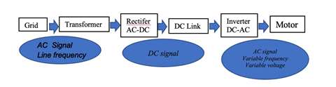 Figure 2 – VFD Block Diagram
A simplified idealization of how a rectifier works is provided in Figure 3, taken from Williams, et. al. [47]. It is seen that there are four diodes placed in a bridge configuration, each of which is oriented so that current can only flow in the upwards direction. When the input signal from the grid is “positive” (i.e., the voltage at terminal A is larger than that at B), current flows through diodes 1 and 2 and a positive voltage is applied to the top side of the DC-link capacitor. During the other 180 degrees of the input signal (i.e., when the voltage is “negative”), diodes 1 and 2 close and current flows through diodes 3 and 4. Thus, once again, a positive voltage is applied to the top side of the capacitor. In this way, the AC signal from the grid is converted into an approximate DC signal.
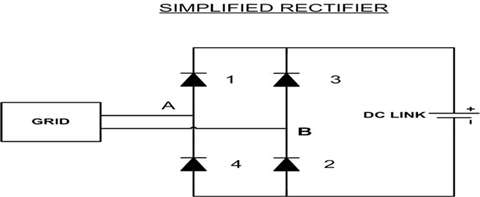 Figure 3 – Simplified Rectifier (Courtesy of Williams, et. al. [47])
Of course, the motors of interest to the reader have three phases, not two, but the principle is the same. Figure 4, taken from API 684 [4] shows a rectifier designed for a three-phase motor. It is seen that there are now six diodes in the circuit. This is the most basic rectifier available, and is known as a six-pulse rectifier. At any given instant, there are two diodes conducting while the other four are “off.” During one full cycle of input voltage, there are six different pairs of diodes conducting, such that each pair conducts for 60 degrees. Because of this, the output waveform is not a pure DC signal, but, instead, consists of six “pulses,” as is also shown in the figure.
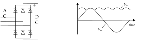 Figure 4 – Six-Pulse Rectifier (Courtesy API 684 [4])
Higher pulse numbers can be obtained by “stacking” multiple six-pulse rectifiers together. For instance, a 12-pulse rectifier is obtained by combining two six-pulse rectifiers, and offsetting the thyristor firing angles by 30 degrees. The number of pulses is simply the number of commutations that occur during one cycle of input voltage – the higher the number of pulses, the smoother the DC signal will be.
The function of the DC-link is to make the DC waveform as smooth as possible so that the inverter is fed a flat DC signal. In order to accomplish this, the DC-link is composed of one or multiple energy storage elements (either capacitors or inductors). When the voltage or current being fed to the inverter drops for whatever reason, the DC-link supplies the missing energy in order to make the signal as constant as possible. A second function of the DC-link is to isolate the grid-side of the system from the motor-side. When those two are not adequately isolated, inter-harmonic excitations, which are described in an upcoming section, can arise.
The inverter is probably the most sophisticated component in a drive. Once again, Reference [47] provides a simplified illustration of how inverters work. As is seen in Figure 5 (taken from Reference [47]), the most basic inverter consists of four switches. If switches 1 and 4 are commanded on (while 2 and 3 are off), positive DC-link voltage is applied to the motor terminals (i.e., the voltage at terminal A is greater than that at B). On the other hand, if switches 2 and 3 are turned on (while 1 and 4 are off), negative DC-link voltage is applied to the motor terminals. The output of this ultra-crude inverter is a simple square wave.
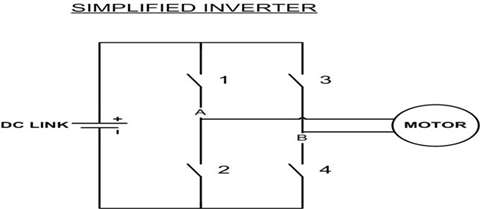 Figure 5 – Simplified Inverter (Courtesy of Williams, et. al. [47])
The simplest inverter, the six-step inverter, is simply the three-phase version of the crude inverter depicted in this figure. The output of such an inverter is similar to that of a six-pulse rectifier, in that it consists of six pulses per cycle. Accordingly, these are also referred to as six-pulse inverters. These inverters are still used in modern current source inverters and load commutated inverters.
However, in voltage source inverters, the inverter usually employs a much more sophisticated algorithm, known as pulse width modulation (which is discussed in the next section) to provide signals to the motor. In pulse width modulation, instead of trying to approximate a sine wave using six pulses per cycle (as is done in six-step inverters), several hundred voltage pulses are used. It doesn’t take much imagination to realize that the output of such a device would be much closer to an ideal sine wave than that from a six-step inverter.
Per Williams, et. al. [47], in addition to its inability to generate an accurate sine wave, the six-step inverter is also unable to control the voltage being fed to the motor. Thus, the voltage is controlled by the rectifier, which then must employ thyristors instead of diodes. A thyristor is similar to a diode except that instead of automatically turning on when the voltage is “positive,” the thyristor has a “firing angle” which can delay turn-on for as long as desired. Thus, the thyristor’s firing angle can be adjusted to provide the desired voltage to the motor (the longer firing is delayed, the lower the output voltage). This leads to one of the paradoxical rules regarding VFDs. In general, if the drive has a sophisticated inverter, it will often be accompanied by a simple rectifier. Conversely, if the inverter is simple, the rectifier usually needs to be more complex.
Part two is available here.

About the author:
Mark A. Corbo, P.E. is the President and Chief Engineer of No Bull Engineering, a high technology engineering/consulting firm located in Bradenton, Florida. In this position, he provides rotordynamics and torsional vibration analyses to various clients in the compressor industry. Corbo has B.S. and M.S. degrees (Mechanical Engineering) from RPI. He is currently serving as the Torsional Vibration Chair on the API 684 Rotordynamics Task Force and his week-long training course, “Practical Rotordynamics for Real Machinery,” which he collaborates on with two other consultants, is considered by many to be the finest in the world.
MAGAZINE
NEWSLETTER


CONNECT WITH THE TEAM