

VFDs – The torsional analyst’s best friend or worst enemy? Part 2
April 22, 2022
Note: This paper was first presented at the Gas Machinery Research Council 2021 Gas Machinery Conference in Louisville, Kentucky in October 2021. Because of the original length of the paper, it has been divided into multiple parts.
The three main types of VFD
Although there are more VFD design types than could possibly be enumerated herein, almost all that are used in the compressor world fall into one of the three following categories:
- Current Source Inverter (CSI)
- Load Commutated Inverter (LCI)
- Voltage Source Inverter (VSI)
In a CSI, and its closely-related cousin, the LCI, the motor input parameter being controlled is the current. Accordingly, the DC-Link in these designs is the energy storage element for current, an inductor. Conversely, in a VSI, the controlled parameter is voltage, and the DC-Link is a capacitor, or bank of capacitors. Thus, although schematic diagrams for VFDs are often indecipherable for mechanical engineers, the basic type can be discerned by simply looking at the DC-Link. If an inductor, it’s a CSI or LCI and if a capacitor, it’s a VSI.
Per Huetten, et al. [22], both basic types have specific advantages and disadvantages, and the selection is based on power and voltage range, complexity, and the reference situation. In general, VSIs are used for the lower power ratings up to 25 MW and the LCI/CSI is preferred for the higher power ratings up to 120 MW. In the range of 15-25 MW, both architectures can be used.
Reliable technology
In general, the LCI/CSI topology, which has been in use since the 1980s, is a mature technology that is known for reliability. The only major difference between the two is that LCIs are only used with synchronous motors while CSIs are employed with induction designs. Conversely, VSIs often provide efficiency advantages, and, when combined with modern control schemes, better dynamic performance. However, they represent a much newer technology, and can sometimes be unpredictable and unreliable.
As previously discussed, CSIs are relatively simple as they often employ six-step inverters which use thyristors as the switching elements. Their rectifiers usually also utilize thyristors, whose firing angles are utilized to control the current/voltage level being fed to the motor.
LCIs are a particular type of CSI. Like CSIs, LCIs use thyristors as the switching elements in the inverter. As stated previously, thyristors can be actively switched on but cannot be actively turned off. Thus, the switch-off is obtained by diverting the current to an alternate path and applying a reverse voltage across the thyristor. If the LCI’s load (i.e., the motor) has particular attributes (i.e., a leading power factor), this commutation can be achieved by simply switching the next thyristor on. This will cause the current to flow in another phase and a reverse voltage to be applied across the thyristor to be turned off. This voltage is the load voltage, which is where the name “load commutated inverter” comes from. Since this scheme will only work if the load has a leading power factor, LCIs can only be used with synchronous motors. Induction motors, with their lagging power factors, are not an option.
VSIs are significantly different from CSIs and LCIs. VSIs can be found with many different topologies and numbers of output levels. The number of levels is simply the number of discrete values that the phase voltages being fed to the motor can have. In the most basic inverter (two-level), each of the output phases can be fed with only two different levels of voltage – DC-plus and DC[1]minus. The next most sophisticated design is the three-level inverter, also known as the neutral point clamped (NPC) inverter, in which each of the output phases can be fed with three different levels of voltage - zero, DC-plus and DC-minus. This design is so-named because the diode clamps are connected to the midpoint (or neutral point) of the DC-Link capacitor. The next most common design is a five-level inverter. It should be noted that whenever there are more than three levels, the additional levels come with the disadvantage that the rectifier needs to be actively controlled. An actively controlled rectifier is more expensive because it requires “active” devices (i.e., IGBTs or IGCTs) instead of “passive” diodes or thyristors.
Pulse width modulation
The large majority of VSIs use pulse width modulation (PWM) to control the voltage being fed to the motor. The basic idea of PWM is illustrated in Figure 6, taken from Hughes and Drury [24], where the parameter of interest is the voltage across the two ohm resistive load. This voltage is controlled by continually moving the mechanical switch between the “on” and “off” positions. The length of time that is spent in each position determines the average voltage across the resistor. The voltage across this resistor can be varied anywhere from 0V (switch off all the time) to the supply voltage of 12 V (switch on all the time). For instance, if a load voltage of 9 V is desired, the switch needs to be in the “on” position for 75% of the time.
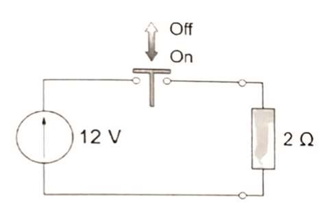 Figure 6 - Chopper circuit (Courtesy of Hughes and Drury, [24])
This circuit is called a “chopper” because the battery supply is “chopped” on and off. A constant switching frequency is usually used, and the width of the “on” pulse is varied to control the mean output voltage. The load is alternately connected and disconnected from the supply by means of an electronic switch, and any voltage up to the supply voltage can be obtained by varying the ratio of “on” time to “off” time. This concept is referred to as pulse width modulation (PWM).
Although an electric motor is hardly a resistive load (it is primarily inductive), the same concept is used to control the voltage being fed to the motor. PWM is employed because the output of a VFD necessarily consists of pulses – the switches in the inverter are “digital” in that they are either fully on or fully off. Thus, the voltage coming from the DC-link is “chopped” into a series of pulses that are fed to the motor at a very high rate, referred to as the switching frequency. In any given region, the pulses are all exactly the same height – the only thing that is varied is the amount of time they are “on” for, or their “width.” By using a large number of pulses (i.e., high switching frequency), the VFD output signal will be at the desired voltage level. Since a high switching frequency is required, the only devices that can be used in the inverter are IGBTs and IGCTs – diodes and thyristors are far too sluggish for this duty.
Controlled frequency
In addition to voltage, the VSI also controls the frequency being fed to the motor. Holopainen, et. al. [19] explain that this is done by varying the pulse pattern in a sinusoidal manner at the desired output frequency. In other words, the same pulse pattern is used in each cycle of the output voltage waveform. As one can easily imagine, if the number of pulses were infinite, the drive would be able to generate a perfect sine wave. Since the number of pulses are finite, this is not achievable. But it is intuitive that the more pulses that are used, i.e., the faster the switching frequency is, the closer the output will approximate a sine wave.
In that vein, Weber, et. al. [46] state that in order for PWM to be effective, the switching frequency of the IGBT modules must be at least ten times greater than the desired frequency to be applied to the motor. In general, switching frequencies are normally in the range of 800 to 20,000 Hz. PWM can be either non-synchronous or synchronous. In non-synchronous PWM, the switching frequency is held constant, and is not related to the frequency being fed to the motor. In synchronous PWM, the switching frequency is variable, and is always kept a specific (large) integer multiple of the VFD output frequency. In general, synchronized PWM provides a “cleaner” signal from the standpoint of torsional vibration. In a recent project, the author noted that changing from non-synchronized to synchronized PWM reduced the torsional excitations by an order of magnitude. Additionally, one of the remedies to the problem reported by Tsukakoshi, et. al. [43] was to switch from non-synchronized to synchronized PWM. However, non-synchronized PWM is less expensive and the one more commonly encountered.
It should be noted that there is one other type of VFD that has not yet been discussed. This type of drive is referred to as a slip-frequency recovery drive. In Corbo and Malanoski [8], the author referred to these drives as static-Kramer drives. These drives, which are only used with wound rotor induction motors, do not vary the electrical frequency being fed to the motor (which controls the stator frequency). Instead, they control the rotor frequency by varying the slip. Per Frei, et. al. [15], the shaft speed is varied by phase angle control or by means of a cascade circuit. Since the author has not encountered one of these in about two decades, they are just mentioned for the sake of completeness.
Voltage distortion
If a VFD were “perfect,” the voltage and current signals being provided to the motor would be perfectly sinusoidal. However, since some distortion always occurs during rectification and inversion, all VFDs will generate voltage and current waveforms that contain harmonic distortion. While voltage distortion is not of much concern to the torsional analyst, current distortion can be a major concern, as it can lead to pulsating torques in the motor air-gap that can generate torsional vibration in the mechanical drive train.
This harmonic distortion is often referred to as “ripple.” Ripple occurs because the current being fed to the motor is not a perfect sine wave. Streicher and Olive [39] explain that if a waveform is a perfect square wave, it will contain all of the odd numbered harmonics out to infinity. They further explain that if the top and bottom halves of the waveform do not look like each other (i.e., are asymmetrical), even harmonics are also present. However, even harmonics in current are seldom produced by VFDs. Additionally, they do not produce any harmonics that are multiples of three, also known as triplen harmonics, because of the fact that the motor has three phases. In general, the largest current harmonics are the fifth and seventh, which Streicher and Olive [39] refer to as the “problem child” harmonics.
The concept of ripple can be confusing since there are two distinct kinds – current ripple and torque ripple. Adding to the confusion is the fact that the two types of ripple have different harmonic numbers, which always differ by plus or minus one. That is, the fifth and seventh harmonic current ripples generate a sixth harmonic torque ripple. Likewise, the eleventh and thirteenth harmonic current ripples generate a twelfth harmonic torque ripple. Readers interested in understanding why this is so should see Walker [45] or Terens and Grgic [41].
In the author’s experience, the electrical engineers at the VFD supplier tend to think in terms of current ripple. Conversely, since the torsional analyst needs to know the torque ripple that is exciting the train, that is the parameter of primary interest to him or her (while current ripple, indeed, generates torque ripple, it is the latter parameter that needs to be known in order to perform a torsional analysis). Thus, when dealing with the VFD supplier, the analyst must insist on obtaining data on the torque ripple generated by the VFD. If this is not made clear, there is a strong likelihood that the data provided by the VFD supplier will be for current ripple, which is not of much use to the analyst.
Current source inverters (CSIs) generate two primary types of torsional excitations, as follows:
- Harmonic excitations
- Inter-harmonic excitations
The frequencies of the harmonic excitations are given by the following equation:
Fexcite = pi * fvfd * 1, 2, 3.... (2)
Where:
Fexcite = Excitation frequency applied to the torsional system, Hz
fvfd= VFD output frequency, Hz
Pi= Number of pulses in inverter
Thus, for the most basic inverter, which has six pulses, we get the familiar result that the excitations are at 6, 12, 18, etc. times the VFD output frequency. Since this frequency is proportional to speed, these excitations are also proportional to speed, which means they appear as positively-sloped lines on the Campbell diagram. It should be noted that many engineers erroneously think that this yields excitations at 6, 12, 18, etc. times running speed on the Campbell diagram. However, that only happens to be true when dealing with a two-pole motor. In general, the order numbers on the Campbell diagram corresponding to these excitations are given by the following:
Nord= 0.5 * pi * Np * 1, 2, 3.... (3)
Where:
Nord= Order number on the Campbell diagram
Pi= Number of pulses in inverter
Np= Number of poles in motor
Dependent on speed
As shown in Hudson [21], the amplitudes of the harmonic excitations are strong functions of VFD output frequency, thereby, making them strongly speed-dependent. Accordingly, when dealing with CSIs, the VFD supplier should provide the amplitudes of the various harmonic excitations (as percentages of motor rated torque) in tables for various VFD output frequencies. Unfortunately, it is common to only receive info. for the harmonic excitations at one speed, usually rated speed (which normally corresponds to grid frequency). The reader should be cautioned that this is not always conservative, as the author has often seen cases where the harmonic excitations at one or more intermediate speeds are higher than they are at rated speed. Dickau and Perrera [11] illustrate this, describing a CSI whose sixth harmonic excitation was max at a VFD output frequency of 24 Hz (or at 40% of the 60 Hz line frequency). Hudson [21] amplifies this point, providing CSI data where the peak for all harmonics was at 40% of rated torque or lower.
Sheppard [32] states that the amplitude of the sixth harmonic can be as high as 20 to 30% of motor rated torque. Murphy [29] gives exactly the same values. However, improvements in VFD design in the time since these references were written make it unlikely that an excitation this large would be observed in a modern CSI.
Kaiser, et. al. [25] performed a torsional analysis of a VFD-driven horizontal pump, and used harmonic excitations of 6X, 12X, 18X, and 24X for the VFD. Based on info. from the VFD supplier, the amplitudes of these were assumed to be 2.0% (6X), 1.5% (12X), 2.8% (18X), and 1.4% (24X) of static torque. Although the author has seen values higher than these, these are more representative than those quoted by References [29] and [32].
The frequencies of the inter-harmonic excitations for a CSI are given by the following equation [34, 36, 41]:
= pr * m * fline ± pi * n * fvfd (4)
Where:
= Excitation frequency applied to the torsional system, Hz
= Line frequency, Hz
= Number of pulses in rectifier
= VFD output frequency, Hz
= Number of pulses in inverter
m, n = Positive integers
Inter-harmonic excitations
In general, the number of pulses in the inverter and rectifier are usually equal. Because of the negatively-sloped line on the Campbell diagram that results (and the problems that it creates), the inter-harmonics involving the minus sign are usually the most dangerous. Thus, for the basic CSI which employs a six-pulse rectifier and a six-pulse inverter, if m and n are taken to be equal, the excitations are at 6, 12, 18, etc. times slip frequency, fline – fvfd. As is noted by Huetten, et. al. [22], Hudson [21] and Somaini, et. al. [35], the only inter-harmonics that are normally significant are the 6 and 12 times slip frequency ones, with the 6 being the predominant one.
Per Terens and Grgic [41], these inter-harmonic excitations are typically small in magnitude, provided that the dimensioning of the DC-link storage elements is sufficient. The amplitudes of some of these components can, in worst cases, amount to 10% of motor rated torque. Usually, they are less than 3.0% of rated torque. The relative danger of harmonic and inter-harmonic excitations can be seen by examining typical Campbell diagrams for each. Figure 7 shows the primary harmonic excitations for a six-pulse CSI driving a two-pole induction motor, while Figure 8 shows the primary inter-harmonic excitations for the same drive (other excitations of secondary importance are also present, but are omitted from the figures for clarity). The operating speed range is from 50 to 100% speed (1800 to 3600 rpm), which is fairly common.
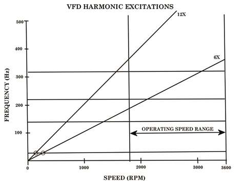 Figure 7 - Campbell diagram showing VFD harmonic excitations
Since the large majority of reported VFD-induced torsional failures have involved the first torsional mode, the locations of the resonances with the first mode are of primary interest. Examination of Figure 7 reveals that the resonances with the first mode generated by the harmonic excitations occur at low speeds, well below the operating speed range. These resonances, therefore, are only transient in nature and are not likely to be dangerous.
Examination of Figure 8 reveals the situation with the inter-harmonic excitations to be drastically different. It is seen that not only are the resonances with the first mode within the operating speed range, they are close to max continuous operating speed (MCOS), where the system’s transmitted torques are highest. This is a very dangerous situation and needs to be considered in the torsional analysis of all VFD-driven trains. Thus, even though their excitation magnitudes are usually significantly smaller than those of the harmonic excitations, the inter-harmonic excitations are often the more dangerous of the two.
Per Sihler, et al. [34], it is important to note that the amplitudes of inter-harmonic pulsating torques are typically low in the nominal speed range of a compressor train – i.e., less than one percent of the nominal torque. This low level of electrical excitation has been confirmed by air-gap torque measurements taken during testing of a 30 MW compression train [34]. However, because of the potential to excite the first mode at a speed close to MCOS, even inter-harmonics having amplitudes less than 1.0% of motor rated torque can be dangerous.
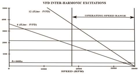 Figure 8 - Campbell diagram showing VFD inter-harmonic excitations
Transient excitations during start-up
Kaiser, et al. [25] studied the level of inter-harmonics produced by various VFD architectures. The magnitudes ranged from as high as 8% for LCIs to less than 1% for PWM VSIs.
All of the information presented on harmonic and inter-harmonic excitations in CSIs is equally applicable to LCIs. However, LCIs have one additional characteristic that makes them more likely to create torsional problems than CSIs – they generate very large transient excitations during the start-up process (similar to synchronous motors).
The LCI cannot start the motor smoothly because it depends on the motor voltage to commutate the inverter thyristors, and there is insufficient voltage to do this below about 10% speed. Consequently, in starting mode, the motor current is applied for a short time, then turned off completely by the rectifier. The thyristors in the inverter recover, and different ones are then gated after which the current is turned on again. Thus, the torque has intervals of zero during this process, so there are relatively large pulsations. Fortunately, this process, which is sometimes referred to as pulse operation mode, stops as soon as the motor reaches about 10% speed.
Per Wolff and Molnar [48], typical harmonic excitations for a six-pulse LCI are as follows: - 6th harmonic – 20% of steady-state torque (100% for 0-10% speed) - 12th harmonic – 5% of steady-state torque (40% for 0-10% speed) - 18th harmonic – 1% of steady-state torque (7% for 0-10% speed) - 24th harmonic – 1% of steady-state torque (10% for 0-10% speed)
Thus, when dealing with an LCI, there are two different modes to consider – pulse operation mode and load commutated mode. Since the excitation torques are much larger in pulse operation mode (see above), that mode is often governing. However, since pulse operation mode is always terminated at a speed below the minimum operating speed, the resonances excited in this mode are transient, not steady-state. Thus, similar to a synchronous motor, whenever there is an LCI in the system, a transient analysis of the start-up condition often must be performed to ensure that the mechanical train can handle the transient resonances occurring during start-up. Corbo and Cook [7] provide a detailed procedure for how to perform such an analysis.
Smaller excitations
Many engineers believe that, from a torsional vibration standpoint, VSIs are not as dangerous as CSIs and LCIs since the magnitudes of their excitations are almost always smaller. This viewpoint is espoused by Kaiser, et. al. [25], who state that, “For all but LCI-type VFDs, state-of-the-art VFD-driven trains should be considered torsionally safe and the torsional analysis of such trains can be omitted.”
With all due respect to the authors of that paper, which is a good one, the author could not disagree with that statement more strenuously. Although their excitations are usually smaller, the excitations arising from VSIs are nowhere near as predictable or well-understood as those from CSI-class drives (this will be elaborated on momentarily). Additionally, the vast majority of torsional failures reported in the technical literature, including those cited herein, over the last 20 years have involved VSI-style drives. Thus, the author believes that, at least at the current time, VSIs are more dangerous than CSIs from a torsional standpoint.
Voltage source inverters (VSIs) generate three primary types of torsional excitations, as follows:
1 Harmonic excitations
2 Inter-harmonic excitations
3 Broadband excitations
Per Song-Manguelle and Nyobi-Yome [36], the frequencies of the harmonic excitations are given by the following equation:
= 6 * fvfd * 1, 2, 3.... (5)
Where:
= Excitation frequency applied to the torsional system, Hz
= VFD output frequency, Hz
Thus, once again, the harmonic excitations are represented by positively-sloped lines on the Campbell diagram and the sixth harmonic is normally the largest.
To read part one, click here
The author

Mark A. Corbo, P.E. is the president and chief engineer of No Bull Engineering, a high technology engineering/consulting firm located in Bradenton, Florida. In this position, he provides rotordynamics and torsional vibration analyses to various clients in the compressor industry. Corbo has B.S. and M.S. degrees (Mechanical Engineering) from RPI. He is currently serving as the Torsional Vibration Chair on the API 684 Rotordynamics Task Force. His week-long training course, “Practical Rotordynamics for Real Machinery,” which he collaborates on with two other consultants, is considered by many to be the finest in the world.
References
[8] Corbo, M. A. and Malanoski, S. B., “Practical Design Against Torsional Vibration,” Proceedings of the Twenty-Fifth Turbomachinery Symposium, Turbomachinery Laboratory, Texas A&M University, College Station, TX, pp. 189-222 (September 1996).
[11] Dickau, R. and Perera, L., “Mechanical Vibration Problems With Variable Frequency Drives,” Proceedings of the International Pipeline Conference, Calgary, Alberta (October 2000).
[15] Frei, A., Grgic, A., Heil, W., and Luzi, A., “Design of Pump Shaft Trains Having Variable-Speed Electric Motors”, Proceedings of the Third International Pump Symposium, Turbomachinery Laboratory, Texas A&M University, College Station, TX, pp. 33-44 (1985).
[19] Holopainen, T. P., Niiranen, J., Joerg, P., and Andreo, D., “Electric Motors and Drives in Torsional Vibration Analysis and Design,” Proceedings of the Forty-Second Turbomachinery Symposium, Turbomachinery Laboratory, Texas A&M University, College Station, TX (October 2013).
[21] Hudson, J. H., “Selection, Design and Field Testing of a 10,500 HP Variable Speed Induction Motor Compressor Drive,” Proceedings of the Twenty-Fifth Turbomachinery Symposium, Turbomachinery Laboratory, Texas A&M University, pp. 25-34 (September 1996).
[22] Huetten, V., Beer, C., Krause, T., and Demmig, S., “VSDS Motor Inverter Design Concept for Compressor Trains Avoiding Interharmonics in Operating Speed Range,” Proceedings of the First Middle East Turbomachinery Symposium, Turbomachinery Laboratory, Texas A&M University, Doha, Qatar (February 2011).
[24] Hughes, A. and Drury, B., Electric Motors and Drives: Fundamentals, Types, and Applications, Fourth Edition, Elsevier, Ltd., Oxford, UK (2013).
[25] Kaiser, T. F., Osman, R. H., and Dickau, R. O., “Analysis Guide for Variable Frequency Drive Operated Centrifugal Pumps,” Proceedings of the Twenty-Fourth International Pump Users Symposium, Turbomachinery Laboratory, Texas A&M University, College Station, TX, pp. 81-106 (2008).
[29] Murphy, S. P., “Application of Variable Speed Electric Motors for Pumps,” Proceedings of the Tenth International Pump Users Symposium, Turbomachinery Laboratory, Texas A&M University, College Station, TX, pp. 157-167 (1993).
[32] Sheppard, D.J., “Torsional Vibration Resulting from Adjustable Frequency AC Drives”, IEEE Transactions on Industry Applications, pp. 812-817 (September/October 1988).
[34] Sihler, C., Schramm, S., Song-Manguelle, J., Rotondo, P., Del Puglia, S., and Larsen, E., “Torsional Mode Damping for Electrically Driven Gas Compression Trains in Extended Variable Speed Operation,” Proceedings of the Thirty-Eighth Turbomachinery Symposium, Turbomachinery Laboratory, Texas A&M University, College Station, TX, pp. 81-91 (September 2009).
[35] Somaini, R., Bidaut, Y., and Baumann, U., “Comparison of Different Variable Speed Compression Train Configurations with Respect to Rotordynamic Stability and Torsional Integrity,” Proceedings of the Forty-First Turbomachinery Symposium, Turbomachinery Laboratory, Texas A&M University, College Station, TX (September 2012).
[36] Song-Manguelle, J. and Nyobe-Yome, J. M., “Pulsating Torques in PWM Multi-Megawatt Drives for Torsional Analysis of Large Shafts,” IEEE (2008).
[39] Streicher, J. T. and Olive, J. J., “Straight Talk About PWM AC Drive Harmonic Problems and Solutions,” Rockwell Automation, Milwaukee, WI (October 2006).
[41] Terens, L. and Grgic, A., “Applying Variable Speed Drives with Static Frequency Converters to Turbomachinery,” Proceedings of the Twenty-Fifth Turbomachinery Symposium, Turbomachinery Laboratory, Texas A&M University, College Station, TX, pp. 35-46 (September 1996).
[43] Tsukakoshi, M., Al Mamun, M., Hashimura, K., Hosoda, H., Sakaguchi, J., and Ben-Brahim, L., “Novel Torque Ripple Minimization Control for 25 MW Variable Speed Drive System Fed by Multilevel Voltage Source Inverter,” Proceedings of the Thirty-Ninth Turbomachinery Symposium, Turbomachinery Laboratory, Texas A&M University, College Station, TX, pp. 193-200 (October 2010).
[45] Walker, D. N., Torsional Vibration of Turbomachinery, New York, NY, McGraw-Hill (2003).
[46] Weber, W. J., Cuzner, R. M., Ruckstadtler, E., and Smith, J., “Engineering Fundamentals of Multi-MW Variable Frequency Drives – How they Work, Basic Types, and Application Considerations,” Proceedings of the Thirty-First Turbomachinery Symposium, Turbomachinery Laboratory, Texas A&M University, College Station, TX, pp. 177-194 (2002).
[48] Wolff, F. H. and Molnar, A. J., “Variable-Frequency Drives Multiply Torsional Vibration Problems”, Power, pp. 83-85 (June 1985).
MAGAZINE
NEWSLETTER


CONNECT WITH THE TEAM