
Tech Corner: Module mounted machinery packages
June 21, 2021
Neetin Ghaisas explores the equipment modularization concept and machinery modules, their structure and the associated benefits.
Many small and large rotating, and reciprocating machinery packages, are mounted on steel structures in the highly modularized facilities.
A module consists of transportable pre-assembly of process plant components designed to minimize site installation and commissioning labor costs. The modularized program has several advantages over the conventional stick-built design approach.
There are many benefits, which encompass being cost-related, quality-related, safety-related and schedule-related.
Cost-related benefits
Allows maximum shift of labor hours from high cost jobsites to fabrication shops or module yards.
Lessens material quantities specifically for concrete, pipe, and cabling with resultant lower total installed cost.
Reduces equipment grouting requirements.
Relocates underground process drainage piping to aboveground shop installation.
Safety- and quality-related benefits
Enables safe engineering practices in the design and layout to be duplicated in future modularization programs, at the same time providing flexibility to optimize space and equipment arrangements to address issues such as transmission of vibration from one machine to other machines that share the same structure.
Improves quality of workmanship due to more controlled production environment.
Minimizes safety risks associated with elevated work and stacking labor.
Reduces material congestion and movement at construction site.
Schedule-related benefits
Allows accelerated construction schedule and makes it possible to advance plant commissioning and start-up activities.
Facilitates parallel execution of fabrication and assembly activities, and lowers the overall construction labor cost due to the differential between field and shop fabrication hourly rates.
Maximizes shop work to reduce weather impacts on productivity from large volume of site work.
Equipment modularization concept
Factors such as the module size and weight, site-specific transportation limits, clearance requirements dictated by operation, maintenance and human factors as well as the benefit-to-cost analysis are helpful in determining the type and scope of machinery strings that can be installed on transportable steel structures.
The concept of machinery modularization generally begins with a study during scope definition phase, which is to assess its practicality before the concept can be developed and accepted for implementation. Usually the prime drivers for module concept study are health, safety and environment (HSE), long-term reliable operation of the equipment and performance requirements. The scope of this study typically includes areas such as the following:
- Clearance space for inspection openings, pull-out lengths, and component removal. Available overhead room;
- Ease of access for operation, maintenance, inspection and testing of on-module equipment;
- Electrical cable routing;
- Environmental conditions at site – minimum and maximum temperatures, effects of wind, ice, snow, and rain on walkways;
- Initial static and dynamic analysis of module structure – including sea and land transportation, if applicable;
- Material handling and movement on-module and off-module;
- Module plot size optimization – address needs for laydown space and extended travel of on-module bridge crane to cover the drop-down area without constraints;
- Mounting heights and orientation – panel displays and valves;
- Noise generated by machinery and contribution from the surrounding auxiliary equipment;
- Noise mitigation;
- On-module lighting and utility stations;
- Potential for release of hydrocarbons and emissions from process and on-module equipment;
- Preliminary operability and maintainability reviews;
- Projections – panel doors, valving, cable trays, conduits;
- Requirements of local, and national (federal) environmental regulations and standards;
- Safe exit or evacuation paths in case of emergency;
- Walkways, ladders, platforms, and railing to reach areas that require frequent inspection, adjustments, recording or maintenance;
Types of modules
Modules can be designed as small, large or very large modules (VLMs).
Small modules are complete components of plants and can be transported by road or rail. Typically, they are complete packaged units that can be placed on prepared foundations and then connected to the adjoining modules. In most cases, they require minimum pre-commissioning activities.
Large modules usually weigh between 100 tons and 600 tons. The upper limit on weight is set by lift achievable at site using conventional rigging methods.
Very large modules weigh in excess of 600 tons. In today’s world-scale ethylene and other hydrocarbon processing facilities, module dry weights can be up to 10,000 tons. They often require non-conventional lifting/jacking and transporting methods. Transportation is often by barge or heavy transport vessel and usually involves use of self-propelled modular transporter (SPMT) to bring the module to its final location and set it in place.
Machinery modules
Some machinery modules have a single deck while other modules include a single deck and a mezzanine floor for the auxiliary equipment. Depending on the specific layout, one machinery string may be installed on a dedicated module or two strings in the same service may be installed in longitudinal or transverse direction on the module’s floor.
For modules that do not have a roof, air-cooled heat exchanger for lube oil may be integrated with the module and mounted on top. Elevated modules allow vertically down oriented process nozzles on compressor casings. This results in unobstructed travel of the overhead bridge crane and is usually the preferred arrangement.
In multibody centrifugal compressor string, the radially split high-pressure casing is located outboard of the low and medium pressure axially split casings to permit removal of the inner bundle assembly. Accordingly, the laydown area is set on this end of the module.
Structural steel mounted pumps and other types of equipment such as positive displacement blowers, centrifugal fans and rotary screw compressors are usually part of the process or packaged equipment modules. Dedicated pump modules typically have pumps in different services installed on its floor. These units are strategically located based on assessment of their dynamic behavior, operating and maintenance access requirements and human factor design aspects.
Large, dedicated modules for rotating equipment packages such as gas turbine driven compressor string typically have an elevated structure, partial or fully enclosed side walls, removable roof and surrounding auxiliaries. Bridge crane and jib cranes are provided to facilitate maintenance and handling. An integrated machinery module project such as this requires breakdown of activities associated with several systems and components.
At a higher level this breakdown identifies responsibilities and locations such as in a module yard or at a job site, for all major scope of work and scope of supply items including shipped loose parts or assemblies.
Obviously, the intent of this effort is to avoid assumptions that can lead to omitted scope and potential delays.
Module structure
Weldable high-strength hot-rolled steel is used for fabrication of module structure. The types of steel sections (whether circular section, I-section or T-section) and their sizes are selected depending upon the base material grades and the imposed loads. Machinery support beams, main trusses, and deck plate girders contribute to module stability and integrity. They are often of welded construction. Galvanized steel is usually required in locations that are prone to corrosion in the long-term.
Ladders, platforms, gratings, handrails, and cable tray supports are designed to provide easy access and ensure safety of people working on the module. These components are mostly connected with high strength bolts and nuts.
Crane runway beams, floor stiffeners, pipe racks and external platforms are sized to impart structural integrity under all static and dynamic loading conditions. They are usually welded.
 The computer-generated image, sourced from Fluor’s internal design. shows the three-dimensional view of a completed equipment module
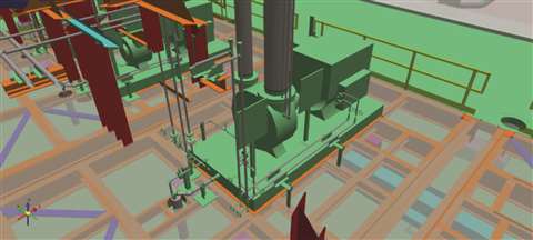 The 3-D view, sourced from Fluor’s internal design, of a Modularized Centrifugal Pump Unit installed on the module floor
Loads on machinery module structure
Loads on module structure are divided into two broad categories, site loads and transportation loads. Site loads comprise of module are dead weight, live loads, environmental loads and operating loads. Transportation loads consist of loads imposed by module dry weight, stowage, wind, vessel hog and sag, ocean waves and vehicle acceleration.
The bulk of the permanent (dead) static structural load comprises weight of the module steel structure, including its attachments and module’s concrete foundation. Machinery train, its on-module auxiliaries, piping and cabling (with conduits or trays) add to the permanent load.
The other types of design loads consist of operating and variable loads, which are specific to the equipment and the site conditions. Some examples of general live loads are concentrated loads on the module’s floor, stairs and roof, if provided. Operating loads are due to fluid weight and its thermal effects on equipment, piping, and piping nozzle loads.
Moving loads on the on-module overhead crane are also categorized as operating loads. Variable loads are the dynamic forces generated by the operating machinery string. Environmental loads are created by various factors such as wind velocity, ice accumulation, snow, seismic conditions and thermal gradients due to site minimum and maximum ambient temperatures.
The other types of variable loads on a module are shock or impact loads during land transportation (load lifting and lowering), acceleration and wind loads realized during ocean transportation, sag of the vessel deck that imposes vertical deflection of the module structure and loads involved during rigging of the complete module in the shop or yard such as during placement on the vessel, offloading from the vessel and installation of the module at site on its foundation. Sea transportation loads arise from peak acceleration forces on module beams due to sway, heave, yaw, roll, pitch and surge.
Machinery module structures are designed for all static conditions, variable loads and operational scenarios such as normal/maximum/transient cases (for example, loss of interference fit of a rotating component resulting in a disintegral rotor) and normal and emergency shutdown situations. Load combinations of dead load and variable loads are also analyzed, and results used to finalize design and sizing of the steel members.
Module structure analyses
Module mounted machinery requires special static and dynamic analyses of the module steel structure to confirm reliable operation of the equipment within acceptable vibration limit throughout the range of its operating conditions, ensure safety of the personnel and maintain structural integrity (stability and permissible deflections of module frame members under the applied loading).
National/federal regulations and local codes and standards have specific requirements for structural design and analysis, the end goal being safety of the facilities and personnel. These requirements are inherited by structural engineers and analysts to design the module structures. The actual calculations methods are outside of the context of this discussion and excluded.
Structural analyses are used to accurately determine deflections under load, relative displacements at shaft ends of the coupled machines and calculate natural frequencies (1x and 2x) of the module structure including mode shapes associated with the frequencies.
The acceptance criteria for static analysis is set by allowable inertia forces on the structure and deflections of the module’s beams and columns under the applied live and variable loads. Machinery supports and interfaces of main columns and beams with module’s deck and roof are subjected to a range of stresses during transportation and operation. They are checked against the acceptance criteria set for cumulative fatigue. A static equivalent analysis is used for loadings that are dynamic in nature such as wind and seismic forces.
Dynamic design aspects of module include mass and center of gravity, stiffness and damping of structure and foundation, applied force, resonant frequency, acceptable amplitude of vibration and rigidity of machine support structure. Dynamic analysis involves effects of mass, stiffness, damping, applied force and deflections.
Potential sources of excitation such as rotor unbalance, coupling misalignment and internal rubs create forcing phenomena. Time-history analysis provides information on mode shapes and frequencies while steady-state dynamic analysis determines resonant natural frequency. The natural frequencies should not interfere and have at least 20 percent separation margin, with operating speed range of the mounted machinery train.
One of the outputs of dynamic response calculated from these excitations is the amplitude versus frequency plots. The maximum permissible vibration amplitudes for rotating machinery, such as API 610 centrifugal pumps fitted with rolling element bearings, are stipulated in this standard. If specified for a given design, the calculated vibration amplitudes at baseplate anchor bolt locations are checked to confirm that they are less than the maximum allowable foundation vibration throughout the machine’s operating speed range.
Strength and rigidity (resistance to deformation) of module structural members are checked in static as well as dynamic analysis.
ISO standard 2631-1 includes general requirements for evaluation of human exposure to vibrations. This is also an important aspect of module design, specifically the areas that are accessed by plant personnel for operation and maintenance activities. It also provides guidance on effects of vibration on health, perception and motion sickness.

About Neetin Ghaisas
Senior Fellow, Rotating Equipment with the Fluor Corporation in Canada. He holds a US patent related to machinery modularization.
Boasting four decades of experience in all aspects of rotating equipment including international experience in petrochemicals facilities (Ethylene, Olefins, Monomers, Polymers, Plastics) and on a wide variety of petroleum and natural gas industry projects that includes expertise in specification development and selection, troubleshooting, rotordynamic reviews and vibration analysis of rotating equipment.
He currently serves positions in API as the Chairman of API 612 standard, Chairman of API 672 standard and member of the Subcommittee on Mechanical Equipment.
MAGAZINE
NEWSLETTER


CONNECT WITH THE TEAM