
Read this article in Français Deutsch Italiano Português Español
Tech Corner: Integrally geared compressor innovations for air separation units
December 19, 2023
By Lukas Biyikli, R&D Portfolio Manager for Integrally Geared, CO2 and Heat Pump Compression Siemens Energy.
For many years, integrally geared compressors (IGCs) have been the technology of choice for air separation plants. This is primarily due to their high efficiency, which directly results in lower specific oxygen, nitrogen, and noble gas costs. However, with the growing focus on decarbonization, new demands are being placed on IGCs, particularly when it comes to efficiency and turndown flexibility. CAPEX also continues to be an important factor for plant operators, especially in small and mid-size applications.
Over the past years, Siemens Energy has initiated several research and development (R&D) projects aimed at enhancing the capabilities of IGCs to meet the evolving requirements of the air separation market. This article highlights some of the specific design improvements we have made and discusses how the changes are contributing to customer goals for cost and carbon footprint reductions.
Air Separation Compressor Application Overview
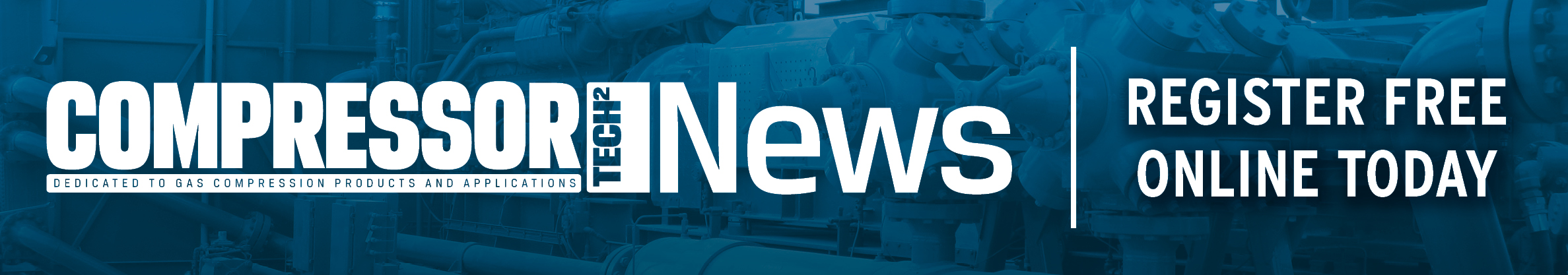
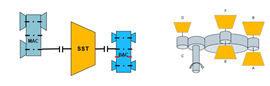
Most air separation plants today feature two compressors: a main air compressor (MAC) and a booster air compressor (BAC). The main air compressor typically compresses the entire air flow from atmospheric to ≈6 bar. A portion of this flow is then further compressed in the BAC to pressures up to 60 bar.
Depending on the power source, the compressors are typically either steam turbine- or electric motor-driven. When steam turbines are used, both compressors are driven by the same turbine via a double shaft end. In the classical configuration, an intermediate gear is installed between the steam turbine and the BAC (Figure 1).
In both electric-driven and steam turbine-driven applications, compressor efficiency is a strong lever for decarbonization, as it directly impacts the unit’s power consumption. This is especially relevant for IGCs driven by steam turbines, as much of heat for generating steam is derived via fossil-fired boilers.
While electric motors offer a more sustainable alternative to steam turbine drives, there is often a greater need for turndown flexibility. Many modern air separation plants being built today have connections to external grids with high penetration from renewables. In Australia, for example, multiple green ammonia plants – which use air separation units (ASUs) to produce nitrogen for ammonia synthesis – are being planned that are expected to draw power from nearby wind and solar developments. In these plants, turndown flexibility will be crucial to compensate for natural fluctuations in electricity generation.
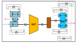 Figure 1 Steam turbine (double shaft end) configuration in air separation plant.
Designing IGCs for the Future
Siemens Energy developed the first IGC in 1948 (formally named the VK). Today, the company has more than 2,300 units built worldwide, many of which are being used in applications with flows exceeding 400,000 m3/hour. Our modern IGCs can achieve rates of up to 1.2 million m3/hour in a single casing. This includes a gearless overhung compressor variation, which can reach pressure ratios of 2.5 or higher in a single stage and up to six when offered in a tandem design.
Some notable design improvements we have made in recent years to target increasing demands for IGC efficiency, turndown flexibility, and CAPEX are outlined below.
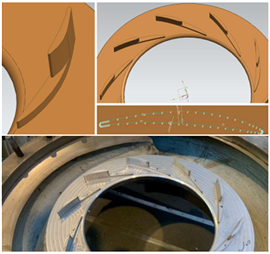 Figure 2 Hybrid diffusor.
4-pinion gear eliminates the need for an intermediate gear between BAC and steam turbine.
Through changes to blade geometry, the polytropic efficiency of the impeller family, which is typically applied for the first MAC stage has been increased. With this new impeller, polytropic efficiencies up to 89% in combination with the conventional LS diffusors have been achieved, and more than 90% efficiency with the next generation hybrid diffusor.
Additionally, the impeller has been qualified for Mach numbers higher than 1.3, which allows for higher power density and pressure ratios in the first stage. It also reduces the power that needs to be transferred by the gear for 3-stage MAC applications, enabling the use of a smaller bull gear diameter and gear casing with a direct-drive first stage.
Next generation hybrid diffusor
The next generation hybrid diffusor can achieve up to 2.5% higher stage efficiency and up to 3% higher turndown compared to a conventional full height vane LS diffusor. The increase is made possible with hybrid vanes (i.e., vanes split into a full height and part height portion). In this configuration,
the flow take-off between impeller and diffusor is reduced by the part height portion of the vane, which is closer to the impeller than the vanes of a conventional LS diffusor. Interactions between impeller and diffusor, which lead to damages at the vanes, are avoided by having the leading edge of the full height vane at the same distance to the impeller, as with a conventional LS diffusor.
The part height portion of the vane being closer to the impeller also improves flow guidance in the area close to surge. As the leading edge of the full height vane portion is still on the same diameter as a conventional LS diffusor, the choke line is unaffected, which results in a broader application/turndown range.
 Compact volutes result in lower material and motor costs.
Wet compression (i.e., water injection)
Water injection involves injecting water droplets into the gas stream in the suction pipe. The droplets evaporate and absorb heat from the process gas stream, thereby reducing the inlet temperature into the compression stage. This results in lower isentropic power requirement and an increase in efficiency by more than 1%.
Gear hardening
By hardening the pinion shaft, the allowable stress per area is increased, which makes it possible to reduce the width of the gear tooth. This leads to a reduction in mechanical losses within the gear by up to 25%, translating into an overall efficiency improvement of up to 0.5%. Additionally, core compressor costs are reduced by up to 1% because less metal is used in the bull gear.
High flow/high head impeller
This impeller can handle flow coefficients (ϕ) up to 0.25 and 6% higher heads than with a 65 degree impeller. Furthermore, the flow coefficient up to 0.25 allows for volume flows up to 1.2 million m3/h and even up to 2.4 million m3/h in a double-flow arrangement in one IGC machine.
The higher phi value enables the use of smaller impeller diameters for the same volume flow, which results in a cost reduction of up to 4% for the core compressor. The impeller diameter at the first stage can be reduced by more
than 5%.
A higher head is achieved by the impeller’s deflection angle of 75°, which increases the circumferential component of the outlet velocity, leading to a higher head as per the Euler equation.
There is a small efficiency reduction with the impeller compared to the high speed/high efficiency impeller due to the higher volute losses. This can be compensated for by having intermediate-sized volute casings. However, even without these volutes, polytropic efficiencies up to 87% can be achieved at a Mach number of 1.0 and a flow coefficient of 0.24.
 BEFORE
 AFTER Figure 4 Turndown capabilities have been improved.
Compact volutes
A smaller volute can avoid collisions with other volutes at reduced bull gear diameter. This can generate cost savings by enabling operators to switch from a 6-pole motor to a 4-pole motor with higher frequency (from 1,000 rpm to 1,500 rpm) without exceeding the maximum allowable bull gear tip speed. Furthermore, it enables less material costs for the volute casing and the bull gear.
In total, up to 2% CAPEX is saved on the core compressor, plus the savings on the motor. As the compact volutes do have a slightly reduced efficiency, the decision to use them is highly dependent on the priorities of the customer (cost vs. efficiency) and should be evaluated on a project-by-project basis.
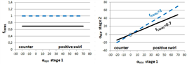
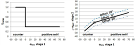
Multiple movable inlet guide vanes (IGVs)
To increase the turndown capabilities, IGVs in front of multiple stages can be installed. This contrasts with past IGC designs, where IGVs were only included before the first stage.
In earlier IGC variations, the swirl factor, which is the angle of the second IGV divided by the angle of the first IGV1 remained constant regardless of whether the flow received a positive (angle > 0°, reduction of head) or a counter swirl (angle < 0°, increase of head). This is disadvantageous, as the sign of the angle changes between positive and counter swirl.
The new configuration allows for two different swirl factors for when the machine is in positive and in counter swirl mode, leading to 4% higher turndown at constant efficiency.
 4-pinion gear eliminates the need for an intermediate gear between BAC and steam turbine.
Reduction of BAC stages and combining MAC and BAC in one machine
By enabling LS diffusors for the typical applied impellers in BACs, the polytropic stages efficiencies could be increased to up to 89%. This, in combination with other efficiency improvement measures, enabled a stage count reduction in BACs, while maintaining the same total train efficiency. The reduction in stages results in a cost saving of 10% for the BAC by eliminating the need for one intercooler, plus respective process gas piping, along with rotor and stator parts. It can furthermore enable the combination of the Main Air and Booster Compressor in one machine in several cases.
4-pinion gear
As previously mentioned, there is typically an intermediate gear required between the steam turbine and the BAC. With Siemens Energy’s new IGC design, this intermediate gear can be integrated into the gear casing by adding an intermediate shaft between the pinion shaft and bull gear (4-pinion gear). Doing so reduces total train costs (core compressor plus auxiliaries) by up to 4%.
Furthermore, the 4-pinion gear is a more efficient alternative to the compact volute to switch from a 6-pole to a 4-pole motor in large Main Air Compressors, if the volutes would otherwise collide or the maximum allowable bull gear tip speed would be exceeded.
Conclusion
IGCs continue to emerge an efficient alternative to inline compressors in ASU applications.
Their use is also becoming more prevalent in several markets that are important for industrial decarbonization, including heat pumps and steam compression, as well as for CO2 compression in carbon capture, utilization, and storage (CCUS) developments.
Siemens Energy has an extensive history designing and operating IGCs. As evidenced by the R&D efforts outlined above (and others), we are committed to continuously innovating these machines to support unique application requirements and meet growing market demands for lower costs, higher efficiency, and increased sustainability. CT2
MAGAZINE
NEWSLETTER

CONNECT WITH THE TEAM