
Tech Corner: Dry gas seals and centrifugal compressors
March 15, 2021
With respect to dry gas seal retrofits, recompression helps legacy compressors comply with current and future regulations. Gautam Chhibber, Matt Lewis and Randy Moore report.
Centrifugal compressor end-users across the oil and gas industry face a host of challenges in today’s environment. Chief among these include a growing need to conserve costs and reduce carbon emissions simultaneously.
Historically fugitive emissions from centrifugal compressors in natural gas applications have been accepted as a normal part of operation, particularly in the midstream and downstream markets. However, with increasing pressure to decarbonize, many regulatory agencies worldwide are proposing new limits on fugitive emissions.
Canada leads this charge with new federal compressor methane limits set to take effect in 2023. Other markets, including the United States and the European Union, are implementing new and more stringent policies.
Today, nearly all new centrifugal compressor installs feature dry gas seals (DGS). While these units exhibit leakage rates across seals that comply with virtually every region’s current regulations and most, but not all, proposed (ie future) regulations, there are still thousands of legacy compressors in operation across the midstream sector that predate DGS technology and utilize wet oil seals.
With fugitive emission rates as high as 200 cfm (5.6 m3/min), these compressors are at significant risk of non-compliance [1].
This article looks at how this problem can be addressed through either a DGS retrofit and/or recompression. Both options require a relatively low up-front CAPEX investment and represent the lowest possible emissions approach to reduce (and even eliminate) fugitive emissions while improving compressor performance.
 Nearly all of today’s centrifugal compressors install use dry gas seals
DGS vs wet oil seals
All centrifugal compressors feature seals installed around the rotating shaft, which prevent process gas from escaping the compressor casing. Wet seals use circulating oil as a barrier and were utilized extensively up until the 1990s. Since then dry gas seals have been installed on virtually every newly manufactured compressor.
These seals offer numerous technical advantages over wet seal systems, including:
- Improved reliability, less maintenance – Compressors with wet seals require ancillary systems and equipment to circulate and treat oil. These systems are often old and need extensive maintenance. If the oil circulating system does fail, the compressor must be taken offline. Catalyst/oil changeouts can also contribute to outages. This is not an issue with dry gas seals, as complex electro-mechanical systems are not required to support them. The result is fewer failure points and higher uptime;
- No oil ingress – With dry gas seals, there is no oil ingress risk across the seal into the process gas. Thus, the potential for contamination is eliminated and product quality can be maintained;
- No parasitic power losses – Oil circulation equipment, such as pumps, require power to run. Electricity consumption can be as high as 100 kW per hour, depending on the size of the compressor. This is an order of magnitude higher than the electrical load for a DGS system (around 5 to 6 kW), and;
- Reduced emissions – although wet and dry seals exhibit similar leakage rates across the seal face (typically between 2 to 6 cfm [0.05 to 0.16 m3/min]), wet seals generate significantly higher emissions when circulating oil is degassed. In compressors with dual wet seals, fugitive emissions rates between 40 to 200 cfm (1.1 to 5.6 m3/min) are not uncommon. The exact rate is mostly a function of the seal size and operating pressure.
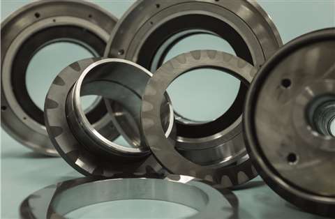
 Siemens Energy’s RF compressor family offers high efficiency and a wide operating range
DGS retrofit
Given the inherent drawbacks of wet seal systems, particularly regarding fugitive emissions, an increasing number of centrifugal compressor end-users have begun looking at options to upgrade their legacy units.
While replacing a new compressor unit equipped with a DGS system would be preferable, it is not a viable option for many across the oil and gas industry whose capital budgets have been slashed amidst the sustained low-price environment. For these operators, a DGS retrofit is a more economical option.
Siemens Energy has been manufacturing and installing API 692-compliant DGS for decades and offers a suite of DGS upgrade solutions for centrifugal compressors. Solutions apply to any compressor OEM/nameplate. They are suitable for inlet pressures of up to 3626 psi (250 bar) and temperatures from -175°F to 482°F (-115°C to 250°C) [maximum seal gas temperature of 320°F (160°C)].
To ensure retrofit compatibility for installed compressors, the DGS cartridge is designed to fit any casing cavity using site tooling. DGS panels and boosters can also be upgraded to meet the latest industry standards. As part of the retrofit, advanced analytics that can assist with diagnostics and digital simulation of the DGS are offered.
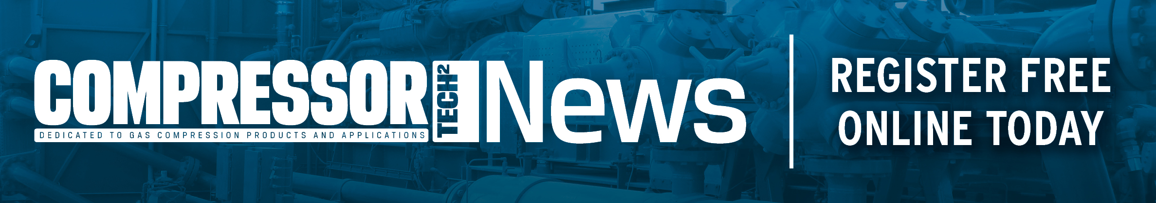
At the heart of the DGS system is a pair of rings. A stationary ring is held against a rotating ring by spring pressure. The rotating ring’s contact face incorporates unique fill-riding geometries in the form of groves or tapered lands on the outer portion [2]. The seals are available in multiple configurations, including:
- Carbon ring process seal - for minimizing clean gas flow and for maintaining a clean process side environment;
- Carbon ring separation seal - for protecting dry gas seals from bearing oil ingress;
- Single DGS - for restrictive applications;
- Double DGS - for lower pressure applications where zero-emissions operation is required, and;
- Tandem DGS - When a lower emission and high-pressure tolerant solution is needed (optional without intermediate labyrinth). Siemens Energy’s tandem DGS upgrade can achieve emissions rates as low as 2 cfm (0.05 m3/min).
- Double and tandem DGS upgrades ensure compliance with all current and proposed emissions regulations, including Europe and the Americas. In certain countries, re-bundling of internals (ie re-aero) of existing compressors are considered a new installation, and previously established emissions limits are no longer valid. In this case then end-users need to replace the DGS to meet the latest regulatory requirements.
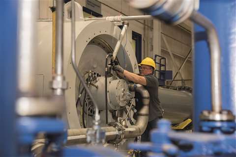
 Greenhouse gas/fugitive emissions recovery via an integrated recompression solution
Driving toward zero emissions
Additional measures must be employed to eliminate fugitive emissions from centrifugal compressors, except for a double DGS configuration. It is relevant for operators who have made commitments to achieve carbon neutrality and decarbonization, although this is currently not a requirement in many markets.
In such cases recompression via an electric motor-driven reciprocating compressor can be used to capture any amount of leakage across seals. The recovered gas can then be injected back into the process stream at the suction or discharge header. This solution is OEM agnostic and applies to greenfield and brownfield installations.
In cases where a gas turbine is used nearby, either as a direct drive for the compressor or electricity generation, the gas can be injected into the fuel inlet. Another potential application is fuel heating. The process gas volume and flow rate will ultimately dictate the size of the reciprocating compressor unit needed for the recompression system.
In all cases, recompression enables zero-emissions compressor operation. It also offers the added benefit of capturing blowdown emissions from station depressurization or scheduled maintenance activities.
During these events, process gas between isolation valves must be vented to the atmosphere or flared. Depending on the compression system, a single depressurization could result in thousands of standard cubic feet of methane emissions. It is not uncommon for this to take place multiple times per year.
Additionally, recompression offers scalability. A single system can be used to capture emissions from more than one compressor, making it a highly cost-effective option for applications with multiple legacy compressors operating in the same service. A stand-by motor-reciprocating compressor can be installed for redundancy purposes.
Conclusion about the DGS system
Historically, conversations surrounding carbon emissions regarding compression trains have focused on those generated from combustion processes, such as burning fuel in gas turbines or gas engines. Blowdown/venting has also been a key area of interest. However, as regulations tighten and operators look to decarbonize voluntarily, fugitive emissions are coming under increased scrutiny.
Whenever possible, end-users should simplify their upgrade projects by engaging with vendors that can handle a large portion of the supply scope. Sole-source provisioning streamlines interface management by enabling one point of contact for critical components, including the DGS system, the recompression system and other ancillary mechanical and electrical systems. It also ensures that synergy and optimization opportunities are identified to minimize costs and emissions to the greatest possible extent.
References
[2] Siemens Energy website, dry gas seals upgrade
Gautam Chhibber. Leads the proposals team. Email [email protected]
Matt Lewis. Proposal engineer. Email [email protected]
Randy Moore. Head of the dry gas seals team. Email [email protected]
MAGAZINE
NEWSLETTER


CONNECT WITH THE TEAM