
Specifying the right transfer switch
April 08, 2022
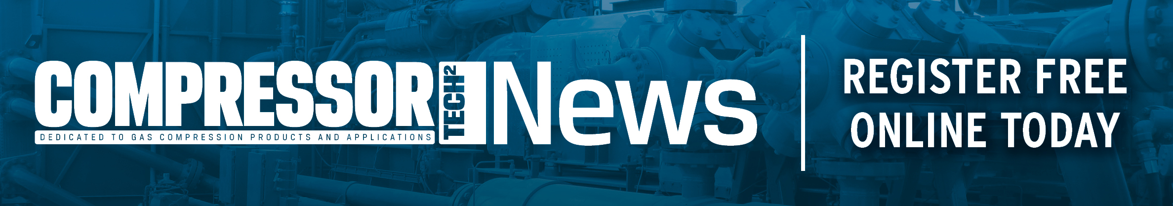
 Automatic transfer switches play a critical role in standby power generation systems and selecting the right switch requires an understanding of the installation requirements and switch options. (Photo: Cummins)
At the heart of any emergency power system is an automatic transfer switch. When grid power fails, the transfer switch detects the power loss, sends a start signal to the standby generator set and connects the generator to facility loads when the generator has reached the proper voltage and frequency. When utility power is restored, the transfer switch returns the load from the emergency power source back to the grid.
Transfer switches are available in a variety of types, each offering its own array of features. Selecting the appropriate transfer switch for a specific application requires a clear understanding of site needs and switch options.
Key considerations
When specifying a transfer switch for a power system, several factors impact the selection of the switch. These factors include:
- Codes and standards (UL, CSA, NFPA, NEMA, IBC, OSHPD, etc.) required.
- The specific application (utility-to-generator, generator-to- generator, utility-to-utility).
- The transition type (open, closed or non-automatic).
- The switch positions (two-position, three-position).
- The number of poles (three- or four-pole).
- The switch type (transfer switch, bypass isolation switch).
- The fault current capability and short-time fault current capability.
Codes and standards
Transfer switches are designed to meet the leading testing requirements specified by UL 1008, the “Standard for Safety - Transfer Switch Equipment.” UL 1008 specifies robust and rigorous testing requirements for verifying manufacturer ratings and ensure reliability and durability. The standard is harmonized with the Canadian CSA C22.2 No.178.1 standard. Any transfer switch product listed to UL 1008 is suitable for use in any application in North America. Transfer switch products without these listing can be challenged in some marketplaces and applications.
Transfer switches are applied in a variety of applications that typically fall into one of four categories defined by the National Electrical Code (NFPA 70): emergency systems, legally required systems, optional standby systems and critical operations power systems. Understanding those categories is important, as they play a critical role in determining what kind of transfer switch is required.
Here’s an overview of each category.
Emergency Systems: These automatically supply, distribute, and control electricity used by systems essential to life safety during fires and other disasters. They include fire detectors, alarms, emergency lights, elevators, fire pumps and public safety communication systems
Legally Required Systems: These systems automatically supply power to a selected set of regulated loads not classified as emergency systems when normal power is unavailable. Examples include critical heating, refrigeration, communication, ventilation and smoke removal
Optional Standby Systems: Supply power to loads with no direct bearing on health or life safety, and are not required to function automatically during power failures
Critical Operations Power Systems: These supply, distribute and control electricity in designated critical areas when a normal power source fails. They include HVAC, fire alarm, security, communication, signaling and other services in facilities that a government agency has deemed important to national security, the economy or public health and safety
Another standard that impacts the selection of the transfer switch is NFPA 110 “Standard for Emergency and Standby Power Systems.” Intended to achieve maximum system reliability, NFPA 110 covers installation, maintenance, operation and testing requirements as they pertain to the performance of the Emergency Power Supply System (EPSS). The requirements cover the performance of emergency and standby power systems providing an alternate source of electrical power to loads in buildings and facilities if the primary power source fails.
The standard differentiates systems by Class, Type, and Level as follows:
Class: The class defines the minimum time, in hours, for which the EPSS is designed to operate at its rated load without being refueled or recharged.
Type: The type defines the maximum time, in seconds, that the EPSS will permit the load terminals of the transfer switch to be without acceptable electrical power
Level: There are two levels. Level 1 systems are installed where a failure of backup power could result in loss of human life or serious injuries. Level 2 systems serve systems and equipment deemed less critical to life and safety.
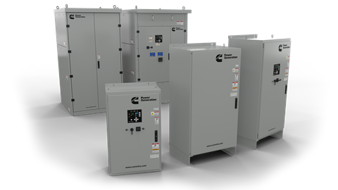
 Transfer switches must have short circuit ratings with Withstand and Closing Ratings (WCR), expressed in RMS symmetrical amperes at a maximum system voltage, and are either be time-based or specific OCPD (breaker/fuse) based. Transfer switches with high time-based short circuit WCR simplifies breaker selection for protecting the transfer switch. (Photo: Cummins)
A system requirement specifying NFPA 110, Level 1, Type 10 cannot be met with a manual transfer switch, making an automatic transfer switch a requirement.
Additional codes to pay attention to include NFPA 70 Article 517, NFPA 99 for Healthcare and OSHPD (Office of Statewide Health Planning and Development – Healthcare in California which also include a seismic element). These standards all call for a UL1008 automatic transfer switch for use in emergency systems and some require a bypass isolation transfer switch.
The International Building Code (IBC) is another code to consider when selecting a transfer switch in the power system. It is important for standby power systems to function after a catastrophic event, such as a hurricane, tornado or earthquake. IBC standards require that critical equipment, such as onsite power systems that power critical branches such as hospitals, police and fire stations, emergency shelters, power plants, airports, government facilities and communications and operations centers, may need to endure higher physical shocks and multi-axis accelerations in certain areas of the United States, including those generated near the San Andreas Fault in California.
Fault current capability
A fault downstream of the transfer switch will result in a short circuit current flowing through the transfer switch, which can cause thermal and magnetic stresses on the switch. As transfer switches are not designed to interrupt fault currents, they must be protected by overcurrent protection devices (OCPDs) on both sources.
To apply transfer switch equipment correctly within its short circuit or withstand and closing rating (WCR), it is first necessary to determine the maximum available fault current from each source at the switch location. Any potential contribution from load sources (motors) must also be considered. Typically, a utility source will have higher available short circuit current, but generators, particularly when multiple generators are used, must also be considered. The withstand and close rating of the transfer switch must be matched to the available fault current.
All transfer switch equipment is required (per UL1008) to have a WCR that is expressed in RMS symmetrical amperes at the maximum system voltage. The WCR must be established by testing rather than through calculations. Ratings can either be time-based or specific OCPD (breaker/fuse) based. Transfer switches with high time-based short circuit WCR simplifies breaker selection for protecting the transfer switch.
Short-time short circuit
Transfer switch manufacturers can take the extra step and perform the UL 1008 optional short-circuit short-time withstand and closing test and subject the transfer switch to fault currents for durations longer than what is listed in the UL 1008 standard. Short-time ratings are similar to WCR ratings, except the duration of the fault is specified by the transfer switch manufacturer.
The difference between the short-time rating and the WCR rating is that the short-time rating requires that the transfer switch pass a temperature rise test at rated load after the short circuit test. In order to apply the short-time rating, the transfer switch must still be functional after being subjected to short circuit current at its short-time rating.
It is important to note that the short-time rating must be withstand and closing rating. Transfer switches listed as withstand rating only violate UL 1008, as the rating is not a true short-time rating.
A typical application for a short-time rated transfer switch is when is when it is applied downstream of a UL1558 switchgear. Since UL1558 switchgear can have a short-time rating of up to 0.5 seconds. Another advantage of a high-short rating is simplifying selective coordination strategies since the transfer switch can carry that short circuit of up to 0.5 seconds allowing downstream breakers enough time to trip and localize a fault.
Pole numbers
Transfer switches are offered in two configurations: a three-pole (the mechanism switches the three phase poles A, B, and C, with the neutral solid) and four-pole (the mechanism switches the three phase poles A, B, C and the neutral).
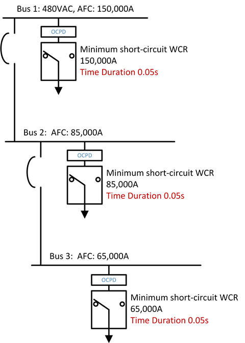
 With simultaneous switching, the neutral pole is mounted on a common crossbar with the phase poles and is switched at the same time as the phase conductors in a break-before-make action. The grounded neutrals of the two power sources are not connected, even momentarily. (Photo: Cummins)
There are two methods of switching the neutral: simultaneous switching and overlapping neutral switching. With simultaneous switching, the neutral pole is mounted on a common crossbar with the phase poles, and thus, is switched at the same time as the phase conductors in a break-before-make action. The grounded neutrals of the two power sources are not connected, even momentarily.
With overlapping switching, the neutral pole is momentarily closed to the grounded neutrals of both power sources in a make-before-break action. A temporary solid neutral connection is created with multiple grounds. Neutral current has, therefore, two paths of return to the source during the overlapping make-before-break switching action and a nuisance trip could result when no ground fault exists.
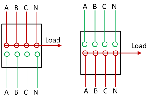
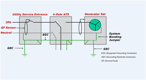 A four-pole configuration transfer switch and ground fault sensing with equipment grounding conductor (EGC) and grounding electrode conductor (GEC). (Photo: Cummins)
Overlapping neutral transfer switches have inherent failure modes which don’t exist in a simultaneously switched neutral product. Specifically, because the neutral pole operates independently of the phase poles, it could fail to transfer completely when the phase poles transfer. Two effects of this failure mode are that the neutral pole could be left disconnected from both sources creating a floating neutral condition, and the neutral pole could be left connected to both sources creating two neutral to ground connections with the potential for ground loops and incorrect earth fault detection. Even with a properly functioning neutral pole there will be a period during transfer when two neutral to ground connections will exist.
To determine which configuration (three- or four-pole) to select, attention must be paid to the system grounding scheme and ground fault protection requirements. If ground fault detection is required on either source, a four-pole transfer switch is necessary in most cases.
As transfer switches are the last link between power sources and loads, selecting the appropriate switch for a specific application requires a clear understanding of site needs and application restraints.
This article is condensed from the white paper “Specifying the Right Transfer Switch,” by Hassan Obeid, Global Technical Advisor - Systems and Controls, at Cummins in Minneapolis, Minn. See the complete white paper at https://mart.cummins.com/imagelibrary/data/assetfiles/0070591.pdf
MAGAZINE
NEWSLETTER


CONNECT WITH THE TEAM