
Read this article in 中文 Français Deutsch Italiano Português Español
Seal gas boosters and heaters in dry gas seal support systems
January 27, 2023
Dry gas seals provide an effective, reliable, and robust standard sealing solution for compressors in all types of processes used in petrochemicals, natural gas, and petroleum industries. They require a continuous or uninterrupted supply of clean and dry seal gas at the design flow and pressure spectrum to ensure the seal faces are lifting off at optimal levels for the best achievable performance. Both pressurized and unpressurized dry gas seals utilize clean “seal gas” upstream of the dry gas seal to establish a barrier against the potentially contaminated process stream.
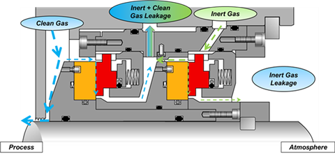 Figure 1: Tandem Dry Gas Seal with Intermediate Labyrinth (All images courtesy of Flowserve Corporation)
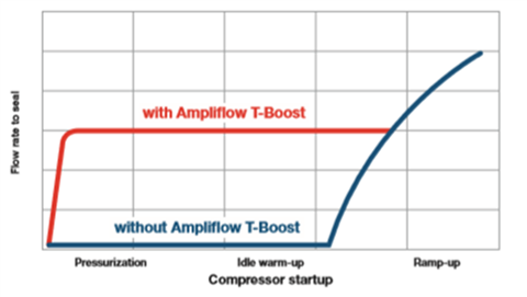 Figure 2: Seal Gas Flow with and without Pressure Boosting Device during start-up of a Centrifugal Compressor
This paper presents a qualitative overview of dew point management and seal gas pressure boost systems that are integral to the reliability of dry gas seals. The focus of discussion is on dry gas seals in centrifugal and integrally geared compressors; however, the outlined principles are also applicable to positive displacement type rotary compressors.
Seal gas boosters
Under normal operating conditions, compressors can provide a continuous supply of seal gas from a higher-pressure level in the compressor, typically from the final discharge nozzle of the compressor. Dry gas conditioning systems receive this gas, filter, and condition it and provide to the dry gas seals.
However during start-up, pressurization, recycling, standstill and shutdown periods, differential pressure across the compressor drops, interrupting seal gas flow. When this occurs, it can lead to migration of unclean process gas with resulting contamination, and degradation of the seal’s performance, which collectively cause unsafe operating conditions, machine downtime and possible higher maintenance costs.
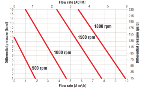 Figure 3: Electric motor Driven Seal Gas Booster Performance
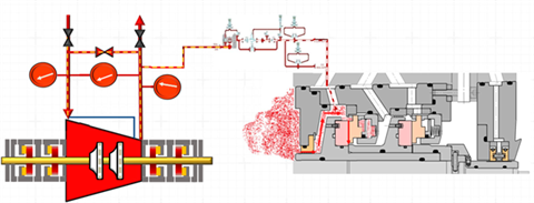 Figure 4: Process Gas Migration to Dry Gas Seal Cavity During Recycle Mode of Operation
Figure 1 shows a cross-sectional view of a typical tandem dry gas seal with intermediate labyrinth and Figure 2 depicts typical flow profiles with and without seal gas pressure boost during start-up of a centrifugal compressor.
When a centrifugal compressor is in steady-state operation and develops the pressure differential, clean and dry seal gas is typically provided from its final discharge nozzle to the seal gas system, and onward to the shaft-end dry gas seals. Figure 3 represents an estimated performance of a seal gas booster at 725 psig inlet pressure of a pipeline centrifugal compressor.
The differential pressure across the centrifugal compressor is too low to provide the required seal gas flow rate in recycle, pressurization, start-up, and pressurized standstill (shutdown) conditions. In these situations, seal gas flow to the dry gas seals is lost and process gas migration to dry gas seal cavity via process labyrinth occurs. Figures 4 and 5 show contamination of the dry gas seal environment in recycle mode and pressurized shutdown, caused by reverse flow of the process gas into the seal cavity.
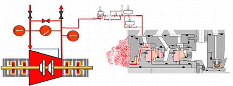 Figure 5: Process Gas Migration to Dry Gas Seal Cavity during Pressurized Shutdown
In the example shown in Figure 6 for a compressor with inlet pressure 1450 psig, the estimated seal gas flow 3.5 cubic feet per minute (cfm) at 56 psid differential pressure is achievable at the operating speed 3500 rpm to avoid contamination in the seal gas cavity.
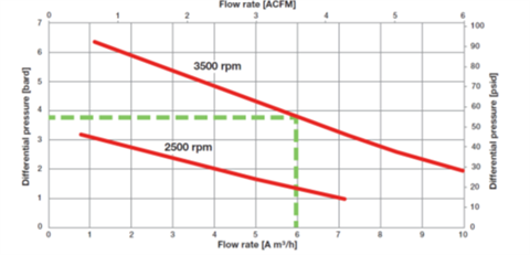 Figure 6: Representative Seal Gas Booster Performance Curve
Modern seal gas boosters are available in two types, pneumatic and adjustable frequency electric motor driven with usual rating s between 7.5 horsepower to 25 horsepower. They provide seal gas during periods of low available differential pressure and help to achieve pressurized protection of the dry gas seals throughout the entire range of compressor operation on its performance map. The differential between the seal gas supply pressure and the sealed pressure should be at least 50 psi to avoid primary seal contamination. Pressure boost ratio of pneumatic boosters varies from 1.2 to 2 based on 3000 psi to 6000 psi maximum allowable working pressures range. The corresponding maximum cycle rates of pneumatic boosters are 100 cycles per minute to as low as 60 cycles per minute. These values are typical and can vary between different models and manufacturers.
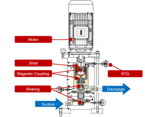 Figure 7: Cross-section of an Electric Motor Driven Seal Gas Booster
Seal gas boosters have become an integral part of the seal gas treatment systems in new installations. They also offer attractive retrofit potential to reliability-focussed hydrocarbon and natural gas processing plants where older seal gas conditioning and support systems might be considered for an upgrade. Figure 7 shows the cross-sectional view of an electric motor driven vertical booster. Note the temperature measuring sensor; a transmitter or RTD sensor with transmitter provided on the containment shell. It is typically mounted between the inner and the outer magnet rings or between the drive magnet and the casing cover. A schematic of seal gas booster is shown in Figure 8.
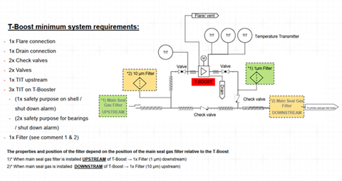 Figure 8: Seal Gas Booster Schematic
Seal gas heaters
The seal gas entering the primary seal area must be clean and dry. API 692, 1st Edition specifies 1 μm spherical particle size with 99.9 % removal efficiency for seal gas filters. In addition to the seal gas quality, at least 35 °F (20 °C) dew point margin (superheat) is essential throughout the dry gas seal system to avoid condensation, loss of sealing pressure, subsequent migration of process gas into the seal cavity and contamination. To ascertain this margin, a phase map computer simulation of the dry gas seal system from the primary seal gas supply point to the primary vent must be carried out to evaluate any potential for seal gas condensation. The temperature of the seal gas must be measured at the point of seal gas entry to the seal, not at the source of seal gas supply. Figure 9 shows some phase map curves.
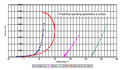 Figure 9 (caption under next graph)
To achieve this seal gas quality, it often becomes necessary to integrate seal gas treatment system(s) with the overall dry gas control system. A seal gas conditioning hardware consists of the units that provide clean and dry seal gas. Coolers, wet gas prefilters and if necessary, a seal gas heater are used to provide dry seal gas. Wet gas demisters and dual filters clean up the seal gas.
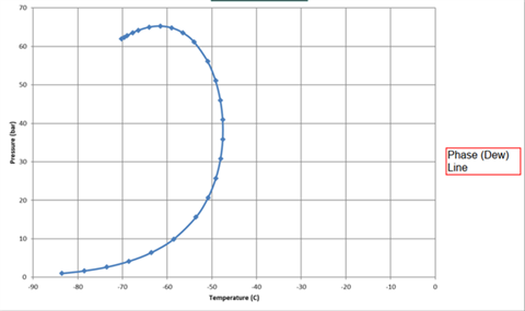 Figure 9: Dew Point Analysis or Gas Phase Map
Direct-type seal gas heater uses an electric immersion heating coil. Indirect type has either an oil immersed heating coil or pressurized seal gas contained inside a spiral coil that is encased in the cast aluminum shell which has the electrical heating elements. This arrangement is favorable in applications where seal gas from the compressor is at elevated temperature or higher dew point. Aluminum serves to transfer heat from the heating elements to the seal gas, thus avoiding direct contact between the two. A seal gas heater integrated with dry gas seal dew point management system is shown in Figure 10.
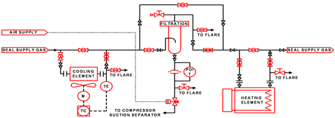 Figure 10: Dew Point Management System
About the authors
Neetin Ghaisas is Senior Fellow - Rotating Equipment in Fluor. He has several years’ experience in turbomachinery with expertise in specification development and selection, troubleshooting, rotordynamic reviews and vibration analysis of rotating equipment. Prior to joining Fluor, he worked as a Machinery Reliability Engineer at Petrokemya (a SABIC affiliate) in Jubail, Saudi Arabia. Neetin Ghaisas holds a MEng. degree from the University of Bombay and is a registered Professional Engineer in the provinces of Alberta and British Columbia in Canada. He has contributed to development of API Standards and Process Industry Practices for many years and currently serves positions in American Petroleum Institute (API) as the Chairman of API 612 standard, Chairman of API 672 standard and member of Subcommittee on Mechanical Equipment. He is also a member of American Society of Mechanical engineers (ASME) and a member of Process Industry Practices (PIP) Machinery Functional Team. Mr. Ghaisas has authored and co-authored several papers which are published in leading international magazines. He holds a US patent related to machinery modularization.
Sourav Majumdar is Manager Compressor Technical Sales - Americas in Flowserve Corporation located at Calgary, Alberta, Canada. Mr. Majumdar possesses 30 years of professional background with significant experience in rotating equipment specializing in compressors and pumps. His expertise is on compressor dry gas seals, seals support systems and seal gas conditioning systems including seal gas boosters. Mr. Majumdar has worked with several end user and engineering organizations globally to help them to select right dry gas / mechanical seals and systems for compressors/pumps, build specification and troubleshooting of such equipment. He holds a degree in Mechanical Engineering from the Indian Institute of Technology -BHU, Varanasi, and a Master of Business Administration (MBA) from University of Leicester, UK.
Acknowledgement
Flowserve Corporation has graciously provided all pictures included in this chapter. The material is adopted from the author’s paper “Dry Gas Seal Systems for Centrifugal Compressors” - Neetin Ghaisas, Sourav Majumdar, CompressorTECH² magazine (June 2017).
References
[1] Flowserve Corporation – Dry Gas Seal Catalogues (various).
[2] API 692, 1st Edition – Dry Gas Sealing Systems for Axial, Centrifugal, Rotary Screw Compressors and Expanders
MAGAZINE
NEWSLETTER


CONNECT WITH THE TEAM