
Improved Modeling For Compressors With Large Tip Clearance
October 31, 2017
This article was originally published in the Aug./Sept. issue of COMPRESSORtech2. We only publish a fraction of our magazine content online, so for more great content, get every issue in your inbox/mailbox and access to our digital archives with a free subscription.
By DR. LEONID MOROZ, ANDREY SHERBINA AND IVAN KLIMOV
Multiple industries have centrifugal compressors supporting the backbone of their operations. Be it turbochargers for automotive applications or compressors for power generation and refrigeration, it is imperative that the turbomachinery not only work, but work well. In a world where technology is consistently improving at an increasingly rapid speed, the modern engineer certainly has their work cut out for them from the moment of initial conceptualization all the way to final calculations. Furthermore, projects that once took years are now expected to be completed in a matter of weeks. As a result, this time constraint increases the risk for error in the early stages of the design process.
This article will focus on the flow in high-efficiency, open centrifugal impellers and how a large tip clearance model applied during the mean-line analysis stage can account for hydraulic losses and ultimately save design time. This has become increasingly relevant in an environment that stresses both competitive turn-around time, accuracy, and ever-increasing operational efficiency. This article will take a look at the technical background behind tip clearance and why it is an important factor in the design process.
As stated above earlier, tip clearance is a source of loss. Traditionally, compressor designers minimize tip clearance and losses associated with clearance flow from pressure to suction side of the impeller. For small, fast centrifugal wheels, the relative tip clearance (The the ratio of absolute tip clearance to blade exit height) can be quite large in contrast with the absolute clearance. This presents a unique challenge since this abnormally high tip clearance can’t be treated with conventional 1-D methods. Because of this challenge, a different type of model must be utilized.

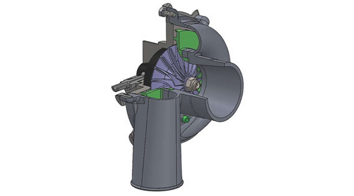
For the purposes of this article, a centrifugal compressor, which consists of centrifugal impeller, vaneless space, vaned diffuser and volute (Figure 1) is the example. The exact value of the tip clearance on the impeller was imposed before beginning the design procedure. This constraint resulted in large relative tip clearance being equal to 0.215 (21.5%). When more traditional methods of design were utilized, namely Aungier’s loss mechanisms, the resulting loss models showed significant discrepancies compared to what prior test data reflected. Specifically, 1D analysis over predicts the pressure ratio by up to 11% at maximal rotational speed. Compressor efficiency was also largely over-predicted utilizing traditional models. At maximum speed, the total-to-total efficiency discrepancy between model and experiment is about 8%. While Aungier loss mechanisms and calculation models are fit for a wide range of compressors, they unfortunately do not work in this case. With this in mind, we must metaphorically go back to the drawing board to figure out what went wrong and what can be changed.

To find the deficiency of the 1-D model system, Reynolds Averaged Navier-Stokes equations (RANS) 3-D computational fluid dynamics (CFD) code can be employed to deal with compressible fluids. In this example, the K-epsilon turbulence model is used for this calculation. The computational grid was generated for the single impeller and vaned diffuser passage by using the structured H-type grid. The volute mesh type is tetra in full volume and prismatic boundary layer. The number of mesh elements for the impeller is 1.64 x 10⁶, for the vaned diffuser is 1.17 x 10⁶ and the volute is 1.21 x 10⁶. Average y+ was kept near a value of 4.06, 3.72 and 5.84 for the impeller, vaned diffuser and volute respectively. This mesh is acceptable for the turbulence model being used. As the boundary conditions, the total pressure and the total temperature were applied uniformly at the inlet boundary. Meanwhile, the mass flow was specified at the volute outlet. Since the flow in the near clearance region was the main subject of consideration, special attention was given to the mesh in this zone. The mesh of quite fine quality in blade tip clearance is shown in Figure 2.
The results of the 3-D CFD simulation are presented here, which demonstrates the particularities of the flow pattern near the tip clearance at the impeller outlet. On the 3-D view, note the back flow zone, which occupies the significant part of the impeller discharge area (Figure 3), and recirculation at the impeller discharge in the meridional plane (Figure 4).

The main conclusions that can be drawn from the 3-D flow study are as follows: When relative tip clearance is very large, d / b2 > 0.11 – 0.12, flow is featured by the increased leakage across the blade in clearance and the back flow in meridional direction near the shroud (Figure 4). The increased leakage across the blade is due to large clearance at the impeller outlet, which leads to addition- al flow deviation from the direction of the blade’s trailing edge. It can be said that part of the blade near the tip losses is deflecting the ability to some degree. The second noteworthy outcome is flow recirculation in the meridional direction and additional work input, which results in the additional enthalpy and entropy raise.
Upon completion of the 3-D CFD analysis and post-processing the results, it can be concluded that the work input into the compressor was over-predicted. The strong leakage across blade tip and large backflow zones cause significant deviation and additional recirculation work input. With this in mind, there is a need to conceptualize this phenomenon into a different model applicable for 1-D analysis.

The existing models account for the loss in tip clearance; the initial simulation results analysis shows the existing models over-predict the discharge pressure. From here, detailed CFD analysis can be suggested to augment existing loss models by correcting the slip, defined as a measure of the fluid slip (the deviation in the angle at which the fluid leaves the impeller from the blade/vane angle in the impeller). By editing the existing model to take into account these two factors (additional flow deviation and flow recirculation) an improved loss model is created, capable of dealing with this abnormal boundary condition (forming the large tip clearance model or [LTCM]).
When applied, this new model seems to correlate well with DoE, and the two speed lines simulated with CFD (Figures 5 and 6) confirm that the loss models system complemented with LTCM results in the correct trend of performance curves.


The simulated compressor efficiency is shown in figure Figure 6. The discrepancy in the simulated results and experimental data reduced due to new model development (maximum difference is 3%).
With a systematic way of performing these calculations accurately, the design process can proceed with full confidence that meanline predictions are accurate and configured to the given boundary conditions. CFD and FEA analysis and rotordynamics can continue from here.
Conclusion
As seen in this article, a new large-tip-clearance model was utilized to improve design and analysis of a centrifugal compressor. While the original, relatively large tip clearance of 0.215 presented a unique challenge, taking the correct steps in the early design stages can result in a quick and smooth development process. In particular, at the preliminary design stage, accounting for the factors of slip and additional heat input provides the ability to design the compressor in a way that has better correlation with experiment and CFD, which results in tremendous savings in design time. As shown, correction of the slip factor was applied in the given example and combined with the additional heat input mentioned. The end result is a market-ready, high-efficiency centrifugal compressor fit for modern application.
About the authors:
Dr. Leonid Moroz is president and CEO of SoftInWay, which he founded in 1999. Contact him at: [email protected]. Andrey Sherbina is lead engineer: Technical Support & Special Projects at SoftInWay. Contact him at: [email protected]. Ivan Klimov is an application engineer at SoftInWay. Contact him at: ivan. [email protected].
References
- Moroz, L., Govoruschenko, Y., Pagur, P., and Romanenko, L., 2008, “Integrated Conceptual Design Environment for Centrifugal Compressors Flow Path Design,” ASME International Mechanical Engineering Congress and Exposition Paper No. IMECE2008-69122.
- Aungier, R. H., 2000, “Centrifugal Compressors: a strategy for aerodynamic design and analysis,” ISBN 0-7918-0093-8.
- Ris, V. F., 1981. “Centrifugal compression machines,” L. Mashinostroenie. 1981. P. 351.
- Danish, S. N., and others, 2006, “The Influence of Tip Clearance on Centrifugal Compressor Stage of a Turbocharger,” 4th WSEAS International Conference on Fluid Mechanics and Aerodynamics, Elounda, Greece, Aug. 21-23, 2006 (pp. 6-11).
- Schleer, Matthias, and others, 2008, “Clearance Effects on the Onset of Instability in a Centrifugal Compressor,” Journal of Turbomachinery July 2008, Vol. 130.
- Tang, J., 2006 “Numerical investigation of the effects of tip clearance to the performance of a small centrifugal compressor,” ASME Paper No. GT2006-90893.
- Backman, Jari L. H., 2007, “Effects of impeller tip clearance on centrifugal compressor efficiency,” ASME Paper No. GT2007-28200.
MAGAZINE
NEWSLETTER

CONNECT WITH THE TEAM