
Dry Gas Seal Systems For Centrifugal Compressors
August 02, 2017
This article was originally published in the June issue of COMPRESSORtech2. We only publish a fraction of our magazine content online, so for more great content, get every issue in your inbox/mailbox and access to our digital archives with a free subscription.
By Neetin Ghaisas and Sourav Majumdar
Dry gas seals are an integral part of modern centrifugal compressors. Specifying engineers sometimes do not give enough attention to the scope, definition and selection of the most appropriate gas seal type, its control system and auxiliaries for a given service application. Several parameters such as the composition, the thermodynamic state conditions of seal or buffer gas, the type of barrier gas, the situations requiring a slow roll, suitability for bidirectional rotation and the system rating must be evaluated before finalizing the design of a dry gas seal system. Ideally, this review should involve the vendor with the unit responsibility, the gas seal manufacturer, and the machinery engineers who work for the machine owner and engineering contractor. Selection of the right type of dry gas seal and its support system contributes to long-term reliability and availability of process plant centrifugal compressor trains.
Some of the key topics discussed in this paper include the principle of operation of dry gas seal faces, the methods of seal gas control, slow roll and challenging sealing environments.
Dry gas seal faces
A dry gas seal consists of a rotating, hard-face mating ring with either a machined or etched circumferential spiral groove pattern and a primary (stationary) ring in softer ma- terial. The primary ring is radially restrained but can move in the axial direction. Under static and depressurized condition, the springs behind the primary ring keep the seal faces closed and in contact. In the static and pressurized condition, the sealed gas penetrates across the faces at the tip of the groove. A sealing dam maintains uniform pressure distribution between the seal faces and helps to provide the hydrostatic lift that results in a low startup torque, lower heat generation, and less parasitic power.

In the dynamic condition, the progressively shallow spiral grooves draw the sealed gas toward the center dam and create gas film pressure to separate the faces so they become noncontacting during running. Special geometry of the spiral grooves provides a uniform hydrostatic and hydrodynamic pressure distribution and maintains the proper seal face gap for gas film stiffness. These features assist in quick liftoff, even during low-speed operation (10 fps [3.05 m/s]) for pressures less than 50 psig (345 kPa guage) and allow the seal faces to adjust rapidly to the changes in the process conditions.
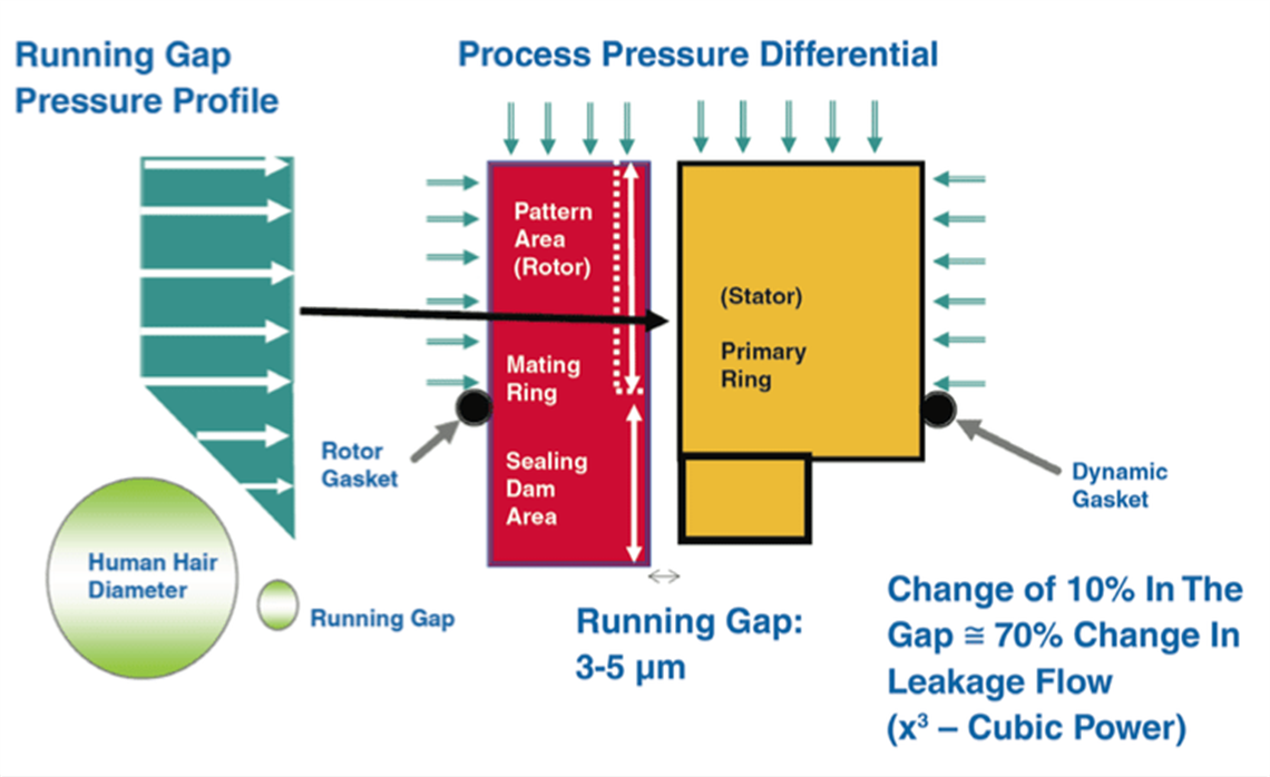
Depending on the shape of the circumferential grooves, the seals can be unidirectional (Figure 1) or bidirectional (Figure 2). A bidirectional seal provides protection from reverse rotation in situations such as the failure of dis- charge check valve and eliminates the need for spare seal cartridges on each end of a between-bearings centrifugal compressor. The spare seal cartridge can be installed at either end of the compressor. A sealing dam and land are shown in Figures 1 and 2. Figure 3 illustrates the pressure profile across dry gas seal faces during dynamic condition.

Slow speed operation of seal faces (slow roll)
The rotors of between-bearings centrifugal compressors, gas turbines and steam turbines experience elastic deflection or bending during standstill condition. The external load, acting perpendicular to the axis of the rotor that results in flexure or bending of the rotor, is either due to gravity force or due to the combined effect of gravity and thermal differential across the rotor based on its operating environment. A slow roll of the driven compressor and driver steam turbine train at speeds from 2 to 500 rpm, including coast down, or ratchet slow roll at 0.125 turn per minute (typically not more than 50 rpm) to gradually relax the bow in the rotors before starting up the train requires the dry gas seals to be designed in a way that provides a face separation during slow roll and in unpressurized or pressurized conditions inside the seal chamber.
The faces of a dry gas seal can contact during slow roll if hydrostatic, or hydrodynamic forces are not adequate to achieve seal face liftoff. The integrity of seal faces that are subjected to contact during slow roll is a function of the rotor speed, dew point of the gas, seal face material properties, contact loading and the duration and frequency of such conditions.


In a noncontacting slow roll, the gas film stiffness is less than during a steady-state running condition. Dry gas seal faces are more susceptible to rubbing if the sealed gas has entrained liquids. The other detrimental conditions include axial displacement of the shaft and reverse pressurization of the inner seal. Partial face contact can occur during coast-down at speeds below the seal face liftoff speed.
By proper balance of the seal face load factor, applied spring force, and friction coefficient of the seal face materials, dry gas seals have been designed to be suitable for slow roll operation at the sealed pressure ranging from 3 to 450 psig (21 to 3100 kPa guage) and axial displacement of ± 0.06 in. (1.5 mm).
Types of dry gas seals
A dry gas seal is essentially a mechanical seal with a rotating mating ring and a stationary seal ring. A representative layout of a dry gas seal assembly and basic seal parts are shown in Figures 4 and 5. The three principal types of dry gas seals for turbomachinery applications are discussed in the following paragraphs. On the inboard of a primary seal, a process gas labyrinth is provided. Both types of primary seal gas control methods, viz., seal gas flow control method and differential pressure control method, ensure positive flow of seal gas across the process labyrinth to avoid reverse flow of the process side gas into the dry gas seal cavity. The source of the seal gas is either a clean process gas, an inert gas or a sweet gas that is compatible with the process gas. A continuous supply of the seal gas at steady-state conditions is essential to proper functioning of the dry gas seal. The seal gas supply pressure should be at least 50 psi (3.4 bar) greater than the highest sealed pressure.

It is a very common practice to use seal gas tapped from the compressor’s discharge. However, positive flow of the seal gas is not available when pressure rise across the compressor is inadequate during process and operational upsets and in other transient conditions such as startup and shutdown. Alternative systems such as Ampliflow can be used to boost the seal gas pressure to help avoid contamination across the primary seal faces.
Single seal
A single-seal design is used in those compressors that handle gases that are neither flammable nor toxic and do not create an environmental harm. Some examples include carbon dioxide, air and nitrogen. A labyrinth-type seal can be added to a single seal to reduce the leakage of the sealed gas in the event of a seal failure.
Double seal
A double-seal design has two opposed seals with a suitable barrier gas introduced at a pressure at least 50 psi (3.4 bar) higher than the sealed process gas pressure. This arrangement is suitable for sealing dirty gases or where external leakage is not permissible (for example, toxic gases and hazardous gases like hydrogen sulfide) or where seal gas consumption must be minimized. A double-seal arrangement is also used in compressors with a limited axial space for the seal cartridge or when compressor suction pressure is close to the vent system pressure. In this case, the seal system is required to be equalized to some intermediate pressure above the vent system pressure. The standard operating pressure limit of double seals is much less than that of single seals and tandem seals.
Tandem seal
A full pressure breakdown occurs across the primary seal faces in a tandem seal arrangement. The secondary or outboard seal normally operates at a pressure lower than that at the primary (inner) seal; however, it is designed to sustain the full pressure if the primary seal fails. The primary vent is routed to the plant’s flare, and the secondary vent is usually led to the atmosphere if nitrogen is used as the separation gas.

A tandem seal with intermediate labyrinth is used to preclude the leakage of process gas to the atmosphere. A clean buffer gas introduced at the intermediate labyrinth at slightly higher than the primary vent pressure creates a differential pressure that helps to keep the process gas from migrating to the secondary seal faces and helps to sweep the leakage of the seal gas in the primary vent and the leakage of the separation gas in the secondary vent (Figure 6). A tandem seal arrangement is more widely used than single and double-seal arrangements in most hydrocarbon and critical process applications.
Separation (barrier) seal
The primary functions of a barrier seal are to prevent the migration of bearing housing lube oil into the dry gas seal cavity and to avoid process gas leakage into the bearing oil. Two common types of barrier seals include labyrinth and segmented dual carbon rings. A carbon ring seal can be of the contacting or noncontacting type. A noncontacting design is preferred to avert localized heat generation and to protect the carbon ring seal against premature wear. A barrier seal should be suitable for bidirectional rotation. Figure 7 shows the arrangement of a carbon ring separation seal in a dry gas seal cartridge.
A clean and dry separation gas is continuously injected into the barrier seal to protect the migration of lube oil from the outboard bearing housing. The separation gas should be filtered to 5 microns solid particles and should be 99.98% free of the entrained liquid particles 3 microns and larger.

Separation gas
Either nitrogen or air is used as the separation gas. Nitrogen, being an inert gas, is recommended as the separation gas for safety reasons. Nitrogen generation equipment should be considered if nitrogen is not readily available at the job site. The majority of the flow through the secondary vent of a dry gas seal is the separation gas together with a very small amount of the seal gas. Air can potentially create an explosive environment in the dry gas seal secondary vent when it is mixed with a combustible process gas. Combustion in the secondary vent can occur if the process-gas-to-air mixture is within the explosive limits and a source of ignition exists in the secondary vent.
If air must be used as the separation gas, the dry gas seal control system should be designed to create either a lean or a rich environment in the secondary vent. This precaution is necessary to minimize the risk of formation of an explosive mixture in the secondary vent. A lean environment is formed by injecting air in the secondary vent, which results in the hydrocarbon-plus-air mixture below the mixture’s lower explosive limit (LEL).
Injecting the process gas into the secondary vent forms a rich environ- ment. It results in the hydrocarbon-plus-air mixture above the mixture’s upper explosive limit (UEL). Typically, the mixtures that have from 5 to 15 % methane (CH4) in air or from 17 to 54% CH4 in O2 are considered explosive mixtures. A fuel/air mixture with less than 5 to 17% of fuel (hence ex- cess of oxidizer) is a lean mixture and a fuel/air mixture with greater than 15 to 54% of fuel (excess fuel) becomes a rich mixture.
The dry gas secondary vent must be routed to the plant’s flare if a rich mixture exists in the vent. The amount of air or process gas required to be injected in the secondary vent is determined from an engineering study and it must evaluate all possible operating conditions, including the primary seal failure situation. Figure 8 shows a graph of hydrocarbon percentage versus molecular weight. The area above the UEL line in this graph rep- resents a rich mixture, the area below the LEL line identifies a lean mixture environment and the area between UEL and LEL lines in this graph is the region of an explosive mixture.
Seal Gas Control Methods
The flow of seal gas to a primary seal is controlled by either a flow control method or a differential pressure control method. The main objective of both types of control methods is to positively sweep the seal gas across the process gas labyrinth to prevent a reverse flow of process gas into the dry gas seal.
A flow-control system controls the supply of seal gas to the seals by regulating the seal gas flow through an orifice upstream of each seal. It includes a valve with a remote flow controller that compares the seal gas flow to each seal and adjusts the flow control valve to maintain a minimum 16 fps (4.9 m/s) flow velocity across the inner process labyrinth seal based on “high select reference pressure” for each seal, measured downstream of the flow orifices.

A differential pressure control system controls the supply of seal gas to the seals by regulating the seal gas pressure to a fixed value (typically 10 psig [70 kPa]) above the sealed (reference) pressure. It includes a differential-pressure control valve with a remote controller. A bypass line with manual block valves is provided around the control valve.
A dry gas seal control system must have an adequate range and controllability to maintain a minimum 16 fps (4.9 m/s) gas velocity across the inner process labyrinth as well as at the labyrinth clearances ranging from the minimum to the maximum and up to two times the maximum design clearance. This is critical to avoid seal face contamination and to maintain the required seal face temperature below the safe upper operating limit. A proper balance of the seal gas consumption and seal gas flow velocity is essential, regardless of the type of seal gas control system used. A high seal gas flow requires more energy and makes the control system inefficient. It also requires relatively larger system components.
A flow control system minimizes the seal gas consumption and can maintain the minimum acceptable seal gas velocity. Except in the double-seal arrangements and in seals with very low sealed pressure (below 100 psig [690 kPa]), a flow control system is usually the ideal choice for all seal types and applications. Also it does not require measurement of the reference pressure that is so critical in a differential pressure control system.
Seal gas conditioning
Seal gas entering the primary seal area must be clean and dry (99.98% free of entrained liquid particles 3 microns and larger) and should be filtered to at least 10 micron solid particles. In addition, at least 36°R (20°K) dew point margin (superheat) is essential throughout the dry gas seal system. To ascertain this margin, a phase map computer simulation of the dry gas seal system from the primary seal gas supply point to the primary vent must be carried out to evaluate any potential for seal gas condensation. The temperature of the seal gas must be measured at the point of seal gas entry to the seal, not at the source of seal gas supply. Figure 9 shows some phase map curves.

To achieve the seal gas quality mentioned above, it often becomes necessary to integrate the seal gas treatment system(s) with the overall dry gas control system. Seal gas conditioning hardware consists of the units that provide clean and dry seal gas. Coolers, wet gas prefilters and if necessary, a seal gas heater, are used to provide dry seal gas. Wet gas demisters and dual filters clean up the seal gas. A unit that boosts the supply gas pressure and creates a sufficient positive differential pressure becomes necessary in many compressor applications in order to avoid seal contamination during transient conditions such as startup, shutdown, process sequence, slow roll, recycle and settle-out. The differential between the seal gas supply pressure and the sealed pressure should be at least 50 psi (3.4 bar) to avoid primary seal contamination.
Figures 10 and 11 show the cross-sectional view of a seal gas heater and a coalescing prefilter. The schematic of a seal gas booster is presented in Figure 12.
Nitrogen, as the source of separation gas, is not available in many remote compressor locations. In such cases, a nitrogen generator can be installed at the job site to provide pure nitrogen (between 95 to 99.5% purity) from compressed air. Most dry gas seal manufacturers offer a nitrogen generator either as a standalone unit or as a unit integrated with the dry gas seal control panel.


Dry gas seal vent system
The primary vent from a dry gas seal system is routed to the plant’s flare when the sealed gas is a hydrocarbon or a hydrocarbon gas mixture. The normal flare pressure is generally close to the atmospheric pressure and the maximum pressure can be as high as 50 psig. If the compressor suction pressure is below the maximum primary seal vent pressure, the seal chambers must be equalized to some intermediate pressure above the compressor suction pressure.
Bypass relief valves provided on the primary seal vent lines should be installed as close to the dry gas seals as possible. The dry gas seal system piping and vents should be sized to prevent over-pressurization of the bearing housings in the event of a seal failure.
The secondary vent from a dry gas seal is routed to the atmosphere unless the hydrocarbon-plus-air mixture is above the upper explosive limit. It is mentioned in the previous discussion that presence of a rich mixture in the secondary vent cavity requires it to be routed to the plant’s flare for obvious safety reasons.
Dry gas seal in cryogenic applications
The materials for the dry gas seal faces, secondary sealing elements and metallic components must be suitable for all operating conditions and the gas composition of the application. As an example, the following factors deserve consideration when selecting the dry gas seals for centrifugal compressors in liquefied natural gas (LNG) service:
• Use of a bidirectional silicon nitride rotating face against silicone carbide/ carbon stationary face (depending on the pressure, size and speed)
• Amorphous diamond-like carbon coating on silicon carbide stationary face to enhance its hardness, lubricity and improve the chemical and thermal stability
• Special Teflon and spring-energized Teflon gaskets and O-rings for cryogenic application
• Low-speed liftoff face technology for the tertiary seals.
• Bone-dry nitrogen rating for the seal (-94°F [-70°C]).
• Flow-control method for the seal gas.
• Flow meters on individual seal gas supply lines.
• A seal gas conditioning system including a booster.
Sulfur contamination
Sulfur is present in chemical compositions such as hydrogen sulfide (H2S) gas. The melting point of elemental sulfur ranges between 235° and 246°F. Sulfur solidification takes place at lower or higher temperatures and pressure depending on its content in a saturated gas. Also in gas streams containing H2S and/ or sulfur vapor, deposition of solidified sulfur can occur because of the chemical reaction supported by catalysts and the changes in pressure and temperature of the gas. One example is the separation of sulfur when H2S reacts with trace amounts (3 to 5%) of oxygen present in nitrogen, which is used as the source of a separation gas. Some possible locations of sulfur deposition in a dry gas seal are shown in Figure 13. Figure 14 includes the images of seal components contaminated by Sulfur.

In centrifugal compressors handling H2S gas, the integration of gas conditioning devices with the overall dry gas seal control system should be considered. The use of a coalescing prefilter to clean up the seal gas and a seal heater to increase seal gas supply temperature to 250°F (121°C) are the two proven effective measures to prevent sulfur solidification and deposition. Similarly, the addition of a booster unit helps to avoid the migration of unclean gas to the seal areas during any transient conditions.

Storage and protection of dry gas seals
The discussion below applies to the seals, which are stored in suitable packaging as well as those which are installed in machines for longer periods of time but have not been put into operation. During the storage period, functionally of essential parts of the seal can be subjected to alteration like aging and distortion. These situations can undermine the seal’s performance. The suggested measures for protection and preservation are listed below.
• The storage place should be dry (relative humidity < 65%) and free of dust. The temperature at the location of the storage should be between 58° and 78°F (14° and 26°C).
• The influences of radiation, heat (direct sunlight), steam and ozone must be avoided. Special storage containers with nitrogen blanketing should be used to protect the seals.
• Corrosion protection agents should not be used as they can have a direct impact on the functionality of the seal.
• Re-qualification of the seal cartridge prior to installation should be considered for storage durations of 36 months or more. The elastomeric secondary sealing elements should be replaced and the seal faces should be checked for alterations, which could have a detrimental effect on the seal’s performance.
• Spare gaskets (gaskets/O-rings not in- stalled and separately packed) should be protected from heat sources such as direct sunlight, artificial light with ultraviolet spectrum and heat-generating fixtures/appliances.
• Gaskets/O-rings should not be stored at temperatures less than 50°F (10°C) and should be warmed to 50°F (10°C) before installation.
• Precautions should be taken to protect stored dry gas seals from all sources of ionizing radiation likely to cause damage to seals and its components.
-
Acknowledgement
All images provided by Flowserve Corp.
About the authors: Neetin Ghaisas, PEng, is senior fellow – Rotating Equipment at Fluor. Contact him at:[email protected]. Sourav Majumdar is general manager, compressor technical sales – North America at Flowserve Corp. in Calgary, Alberta, Canada. Contact him at: [email protected]
MAGAZINE
NEWSLETTER


CONNECT WITH THE TEAM