VFDs – The torsional analyst’s best friend or worst enemy? Part 3
07 June 2022
The criticality of torsional analysis increases when a VFD is used. By Mark A. Corbo
Note: This paper was first presented at the Gas Machinery Research Council 2021 Gas Machinery Conference in Louisville, Kentucky in October 2021. Because of the original length of the paper, it has been divided into multiple parts. Part 2 is shown here.
The primary difference between the harmonic excitations generated by VSIs and those produced by the CSI/LCI drives is that the former are always significantly smaller. For example, Baccani, et. al. [5] reduced the torque ripple of a 30 MW system from 15% to 4% by switching from an LCI to a VSI.
The other significant difference between CSI or LCI drives and VSI drives is the behavior of the magnitude of the harmonic excitations as a function of the load. With CSI and LCI drives, the magnitude almost always depends strongly on the load torque (and, thus, the operating point) but with VSI drives, the load-dependence is usually smaller, and often non-existent.
Per Song-Manguelle and Nyobe-Yome [36], the frequencies of the inter-harmonic excitations generated by the pulse width modulation (PWM) of VSIs are given by the following equation:
fexcite = m * fswitch ± n * fvfd (6)
Where: fexcite = Excitation frequency applied to the torsional system, Hz
fswitch = VFD switching frequency, Hz
fvfd = VFD output frequency, Hz
m, n = Specific positive integers
As was the case with CSIs, the inter-harmonics of most interest are usually the ones that are functions of the difference between the two frequencies. However, in direct contrast to CSIs, where VFD output frequency was interacting with line frequency, in a VSI, the interaction is between VFD output frequency and VFD switching frequency (or VFD carrier frequency, which is equal to switching frequency).
Inter-harmonics are also sometimes referred to as “sidebands” because when an FFT is performed on the torsional signal, the inter-harmonics appear as paired frequencies equally straddling harmonics of the carrier/switching frequency.
The integers m and n obey some rather odd rules. If m is even, then n is simply the multiples of 6, i.e., 6, 12, 18, etc. [36].
If m is odd, then the permissible values of n are defined by the following equation [36]:
n = 3(2i + 1) (7)
Where: i = All non-negative integers
Thus, if m is odd, the corresponding values of n are 3, 9, 15, 21, etc.
VFD-driven torsionals
It should be noted that there is not universal agreement amongst experts on the above equations. In his role as the editor of the Torsional Vibration section of API 684 [4], the author put together a team of about a half dozen of the top VFD experts in the world to help him write a brand-new section on VFD-driven torsionals.
They all worked for different companies in different countries. Whereas these experts were able to give the author a consensus opinion on just about every question he asked, they were not able to come to a consensus on one subject – the inter-harmonic excitations output by VSIs.
The author believes the above equations are the “most correct” because they have a solid theoretical basis, and they were preferred by a plurality of the experts. However, the dissenting experts’ opinions can be understood when the following real-world experience is relayed.
There are plenty of VSIs that don’t strictly obey these equations (for both harmonic and inter-harmonic excitations). Although the VSI’s torque is very smooth when compared with the LCI’s, measurement errors in the drive’s motor current sensors may cause small excitations at the output frequency and twice output frequency.The author has seen these first and second harmonics on a number of VSIs he has worked on.
There have also been occasions where damaging VSI inter-harmonics have been observed between VFD output frequency and frequencies other than switching frequency.
Huetten, et. al. [22] have observed inter-harmonics between VFD output frequency and line frequency in VSIs. Additionally, Adachi, et. al. [1] report on a high lateral vibration problem caused by high oscillating torques in a geared centrifugal compressor train.
However, the source of the air-gap torque pulsation was not the sidebands based on the PWM carrier frequency (4800 Hz). These sidebands were instead based on the control loop frequency (1024 Hz) and sampling frequency (256 Hz) of two microprocessors in the VFD panel.
Additionally, counter to intuition, dangerous inter-harmonics are not limited to small values of m and n in Equation [6]. Tanaka, et al. [40] report problems associated with inter-harmonics having n values as high as 75 and 132. Kaiser, et. al. [25] and Adachi, et. al. [1] describe problems instigated by inter-harmonics having n values of 22 and 30, respectively.
Finally, there have been cases where, although the VSI was known to be causing the failure, the mechanism was not fully understood. As has already been described, Feese and Maxfield [14] discuss such a case, where the oscillating torque in the train was observed to be excessive whenever the VFD was operated at an electrical frequency above the first torsional natural frequency.
Problems with torsional analysis of a train
All of this uncertainty makes performing a torsional analysis of a train being driven by a VSI quite problematic. It is the author’s opinion that unless excitation information for the specific VSI/motor combination in question is available, the analyst would be foolish to simply assume the excitations are per the above equations. Instead, the procedure given in an upcoming section should be employed.
One thing that all of the experts agree on is the inter-harmonic excitations output by VSIs are relatively small in amplitude. Per Adachi et. al. [1], based on the measured lateral vibration and the estimated torsional amplification factor, the excitation torque being output by the VFD was estimated to be 1.3 percent of motor rated torque.
Tanaka, et. al. [40] estimated the max inter-harmonic torque generated by a VSI to be 0.44% of motor rated torque. Sihler, et. al. [34] state that the amplitudes of inter-harmonics are typically low in the nominal speed range of a compressor train – i.e., less than one percent of the nominal torque.
As was mentioned previously, there are two basic forms of PWM – synchronized and non-synchronized. Since non-synchronized PWM involves a constant switching frequency, inter-harmonic excitations involving the switching frequency are more likely to be significant than with synchronized PWM.
The third type of excitation that can occur in VSIs is broadband excitation. The excitations that have been discussed up to this point, harmonic and inter-harmonic, have all involved discrete frequencies that were related to various frequencies in the system.
On the other hand, if the drive utilizes a type of control known as hysteresis control (which will be described later), the excitations are no longer at discrete frequencies. Instead, the excitations occur at all frequencies within the spectrum, which is referred to as broadband excitation. If, in addition, the excitations at all frequencies have equal amplitudes, it is referred to as “white noise.”
White noise spectrum
With a white noise spectrum, the amplitudes are smaller than those of excitations that occur at discrete frequencies. Per API 684 [4], due to its random nature, it is also not capable of generating as large of a torsional response as an excitation having a distinct frequency.
While it may cause the vibration to increase on a temporary basis, it will seldom do it for long. As a result, it is unlikely that the torques or stresses in the mechanical train can build up to a harmful level.
Accordingly, broadband or white noise excitations can usually be safely omitted from the torsional analysis. However, if the analyst chooses to account for these excitations in his or her analysis, Kocur and Muench [27] present a method for modeling them.
It should be noted that there are some sources, such as Ganesan, et. al. [16] who believe that the inter-harmonic excitations are the only ones that need to be included in a torsional analysis.
Their reasoning is that the harmonic excitations are unlikely to excite the first torsional mode within the operating speed range, as was shown in Figure 7. However, while their point is taken, the author believes the harmonics should still be accounted for in the analysis.
That is because there are some failures, such as those reported by Eshleman [12], that were directly attributable to the harmonic excitations.
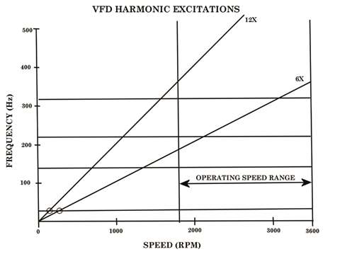 Figure 7 - Campbell diagram showing VFD harmonic excitations
Before this section is concluded, one more thing should be stated about incorporating VFD excitations in a torsional analysis. A typical torsional analysis is done “open loop” – that is the mechanical drive train is treated as being separate from the electrical system and the excitations from the VFD are simply applied to the train model at the location of the motor core.
As is noted by a number of authors, this is not 100% correct, as the interactions between the electrical system and mechanical system should theoretically be included in the analysis. However, Holopainen, et, al. [19] state that the open loop case is usually the worst case because the speed control is often capable of decreasing the torque amplitude when the controller is correctly tuned.
The conventional practice of performing these analyses open loop is, therefore, normally conservative.
VFDs and short circuits
In addition to generating excitations of its own, adding a VFD to a system also complicates the torsional analysis in the area of short circuits. When a fixed speed motor is subjected to a short circuit, it generates torsional excitations at line frequency and, sometimes, twice line frequency.
The situation changes significantly when a VFD is employed, as the electrical frequency being fed to the motor is now variable, not constant. This means that the chances of a resonance being triggered by a short circuit are theoretically greater when a VFD is in the system. For instance, in most motor-driven centrifugal compressors, the first torsional mode, which is the mode most likely to be excited by a short circuit, lies somewhere between 20 and 30 Hz.
This means that in a fixed speed system, short circuit excitations, occurring at 50 or 60 Hz, are not likely to trigger a resonance with the first mode. However, in a variable speed system, it is quite common for the minimum speed to be 50% or less of the synchronous speed, meaning that the electrical frequency could be in the 20 to 30 Hz range when running at a reduced speed.
The implication of this, of course, is that there is often a running speed where the short circuit excitation will be in direct resonance with the first torsional mode. Thus, when a VFD is in the system, short circuits are potentially much more dangerous than in a fixed speed system.
Of course, any analyst who works on VFD-driven systems for any length of time will almost certainly encounter a VFD supplier who will claim that the VFD is “smart enough” to detect any short circuit and shut down the motor before any damage can occur.
Not being an electrical engineer, the author canvassed a number of the world’s top experts in the field on this question during the writing of Reference [4]. The overwhelming consensus was that, while some VFDs can snuff out some short circuits, there are few, if any, VFDs that can catch all short circuits.
Accordingly, it would be foolhardy to rely on this argument as justification for not worrying about short circuits in the design phase.
What short circuits are a concern?
There are two types of short circuits that are of concern when performing a torsional analysis – line-to-line shorts and three-phase shorts. Although there are other types of short circuits than can occur, the worst case is always going to be one of those two.
The bottom line is that while the VFD does provide some protection against line-to-line short circuits in some situations, it provides little to no benefit if the short is of the three-phase type.
Thus, the only thing that can be concluded is that the presence of a VFD decreases the likelihood of a short circuit occurring, as is confirmed by Kaiser, et. al. [25] and Grgic, et. al. [17].
However, as stated previously, the chances of a failure increases when a VFD is present since there is a much greater chance of resonance with the first mode. Thus, short circuit analyses should still be performed when there is a VFD in the system.
Aho, et. al. [2017] concur, stating that too often the short circuit analysis for VFD supplied motors is neglected in contrast to fixed speed motors – assuming that the short circuit torque is limited by the fast reaction of the VFD and its protection functions.
Since the short circuit current and the resulting electromagnetic torque is limited solely by the short circuit impedance of the motor, not by the VFD, short circuit load cases have to be analyzed during the design phase.
Accordingly, the author concurs with API 684 [4] which states that if there is a condition where the motor feed frequency can be within ±10% of the first torsional mode, both line-to-line and three-phase short circuit analyses need to be performed.
Of course, the analysis should be run for the case where the excitation frequency is at resonance, or as close to resonance as possible, with the first torsional mode. In addition to the author, Wachel and Szenasi [44] and Frei, et. al. [15] also make similar recommendations.
VFD control loop instability
The last item of concern is control loop instability. In this phenomenon, the entire control system, consisting of motor, VFD, VFD control system, and mechanical train, goes unstable at one of the train’s torsional natural frequencies (usually the first), resulting in mechanical failures in the train. Instances where this has occurred in the field are documented in Stephens [38] and Del Puglia, et. al. [10].
The biggest issue with this item is, in direct contrast to the previous two, it can seldom be predicted during the design stage. In order to determine the susceptibility of a system to this type of instability, the analyst needs to perform a sophisticated electromechanical control loop analysis on the entire system and evaluate items such as gain margin and phase margin.
Although performance of such an analysis by the torsional analyst is not unheard of (see, for instance, Maragioglio, et. al. [28], Falomi, et. al. [13], or Hernes and Gustavsen [18]), this is far more the exception than the rule. This is because the cost and time required to perform such a rigorous analysis can seldom be justified, except in special cases.
Still, the author believes that all torsional analysts should have some familiarity with this phenomenon. In order to facilitate understanding, one needs to take a cursory look at the different control systems used for VFDs. While it is not critical that the analyst understand these systems in great detail (unless he or she is planning on undertaking the analysis just described), a grasp of the fundamentals is helpful.
![Figure 9 – Block Diagram of VFD Control System (Courtesy Holopainen, et. al. [19])](/Images/480xany/20220607-095947-image.jpg) Figure 9 – Block Diagram of VFD Control System (Courtesy Holopainen, et. al. [19])
Figure 9 – Block Diagram of VFD Control System (Courtesy Holopainen, et. al. [19])
Figure 9, taken from Holopainen, et. al. [19] gives a big picture view of the control system. Ultimately, the goal of the VFD (aka converter) and its control unit is to ensure some process variable (usually pressure or flow) is at its desired value. This is accomplished by controlling the speed of the prime mover.
The speed is in turn controlled by controlling the motor torque. The speed controller of the converter adjusts the torque reference in order to keep the speed equal to the reference speed. Finally, the torque is controlled by the torque or current controllers to be equal to the reference given by the speed controller. Thus, in essence, the primary parameter being controlled is torque.
Control systems for VFDs
There are three main types of control systems for VFDs, as follows:
- Scalar control
- Vector control
- Direct torque control
All three control types interface with the VFD’s inverter to determine the voltage pulses being fed to the motor. From a steady-state standpoint, all three types tend to behave in a similar manner. Their ability to perform under dynamic conditions is what differentiates them from each other.
It should be noted that these three alternatives only apply to VSIs. Almost all drives of the CSI/LCI class utilize some form of vector control. The difference is that while the control system for a VSI interfaces with the inverter, the CSI/LCI control system operates on the VFD’s rectifier.
From a practical standpoint, the biggest difference is that even with a similar style of vector control, the CSI/LCI topology is nowhere near as responsive as is the VSI. This is because the rate at which the torque can be changed is limited by the rate at which the current can be modified.
Since a VSI uses capacitors in the DC-link, the current can be altered almost instantaneously. That is not the case with CSIs or LCIs since their DC-link is a large inductor which introduces a delay into the changing of the motor current.
Scalar control is the simplest form of control – the controlled parameter is speed. Scalar control simply keeps the ratio of voltage-to-frequency being fed to the motor constant, so it is also referred to as “Volts per Hz control.”
The reason why it is desirable to keep the ratio of voltage to frequency constant is the motor’s stator flux is directly proportional to voltage and inversely proportional to frequency.
Since it is desirable to keep the stator flux constant (since the torque is directly proportional to it), when one increases the frequency, one has to also up the voltage commensurately. In most volts/Hz systems, the ratio is held constant from minimum speed to rated speed. This speed range is thereby called the “constant torque” region.
Once the speed is increased above rated speed, it is no longer feasible to continue to increase the voltage – instead, the voltage is held constant at its rated value. Thus, in this region, the stator flux decreases as the speed increases, so this realm is sometimes called the “field-weakening region.”
Since the load torque of devices such as centrifugal compressors, pumps, and fans increases with speed squared, it is often difficult to operate very far above rated speed. Additionally, since flux (and torque) are inversely proportional to frequency (and speed) in this area, power (which is the product of torque and speed) remains constant. Thus, this is also called the “constant power” region.
Open loop control
Scalar control is sometimes also referred to as “open loop control” since it theoretically does not require any feedback from the motor. The only required input is the desired speed. However, Holopainen, et. al. [19] state that, in practice, at least the motor phase currents are measured and used to compensate the resistive voltage drop of the motor windings that tends to decrease the flux at low speeds.
This function is commonly called IR compensation. Thus, although it is referred to as “open loop,” scalar control is seldom purely open loop.
Since it is so simple, scalar control is the least responsive of the various control options. Per Alexander, et. al. [3], scalar control is only acceptable for simple applications such as centrifugal pumps and fans. However, this lack of responsiveness is not entirely detrimental.
Because of this characteristic, scalar control is also less likely to go unstable than its more sophisticated counterparts. In fact, several control instability problems have been solved by simply changing from vector control to scalar control, such as the one reported on by Alexander, et. al. [3].
A more sophisticated control method is vector control, also referred to as “field-oriented control” by Hughes and Drury [24]. In this system, there are two controlled variables – stator flux and motor torque. These are regulated by controlling both the torque and flux-producing components of the stator current.
The control is always closed loop, as the motor phase currents are always measured. Unlike scalar control, the system contains a detailed mathematical model of the motor.
Thus, although it is impossible to actually measure the torque and flux-producing portions of the stator current separately (the total current is all that can be measured), the motor model is used with the measured phase currents to get an accurate estimate of the breakdown.
Per Holopainen, et. al. [19], these are then controlled to be equal to their reference values by current controllers of the PI (proportional plus integral) type. This is achieved by the current controllers selecting the proper series of stator voltage vectors to be fed to the motor (hence, the name “vector control”).
For an explanation of what a voltage vector is and why controlling it is beneficial, the reader is encouraged to consult Hughes and Drury [24] or Holopainen, et. al. [19].
Change in torque
Hughes and Drury [24] explain that if a step change in torque is desired there are only two ways to achieve it – via instantaneously changing either the rotor flux or rotor current. Since a magnetic field always has stored energy associated with it, the first option is impossible.
Thus, the only feasible route is to keep the flux constant and change the current instantaneously. This is accomplished by keeping the flux component of the stator current constant while rapidly changing the torque component.
In order to accomplish this, a fast-acting closed loop current controller is part of the VFD control. Most high performance VFD control units now include such a controller.
There are two basic variants of vector control. In one, in addition to the motor currents, the motor position and speed are also measured via an encoder. In the other scheme, there is no shaft speed encoder, and the only measured parameters are motor electrical parameters.
This scheme is properly referred to as “sensorless vector control” (SVC). However, Hughes and Drury [24] state that this system is sometimes also called “open loop vector control.” This is highly misleading, as the system is definitely closed loop – the measurement of the motor currents is critical to the workings of this design.
Part one is available here
Part two is available here
The author
 Mark A. Corbro, P.E. is the president and chief engineer of No Bull Engineering (Photo: Mark A. Corbro)
Mark A. Corbo, P.E. is the president and chief engineer of No Bull Engineering, a high technology engineering/consulting firm located in Bradenton, Florida. In this position, he provides rotordynamics and torsional vibration analyses to various clients in the compressor industry. Corbo has B.S. and M.S. degrees (Mechanical Engineering) from RPI.
He is currently serving as the Torsional Vibration Chair on the API 684 Rotordynamics Task Force. His week-long training course, “Practical Rotordynamics for Real Machinery,” which he collaborates on with two other consultants, is considered by many to be the finest in the world.
References
[1] Adachi, A., Tanaka, K., Takahashi, N., and Fukushima, Y., “Torsional-Lateral Coupled Vibration of VSD Motor Driven Centrifugal Compressor System at Inter-Harmonic Frequencies in Voltage Source PWM Inverter,” Proceedings of the Thirteenth Asia Pacific Vibration Conference, University of Canterbury, New Zealand (November 2009).
[3] Alexander, K., Donohue, B., Feese, T., Vanderlinden, G., and Kral, M., “Failure Analysis of an MVR (Mechanical Vapor Recompressor) Impeller,” Engineering Failure Analysis, Volume 17, pp. 1345-1358 (2010).
[4] API Standard Paragraphs Rotordynamic Tutorial: Lateral Critical Speeds, Unbalance Response, Stability, Train Torsionals, and Rotor Balancing, API Technical Report 684-1, First Edition (November 2019).
[5] Baccani, R., Zhang, R., Toma, T., Iuretig, A., and Perna, M., “Electric Systems for High Power Compressor Trains in Oil and Gas Applications – System Design, Validation Approach, and Performance,” Proceedings of the Thirty-Sixth Turbomachinery Symposium, Turbomachinery Laboratory, Texas A&M University, College Station, TX, pp. 61-68 (2007).
[6] Bruha, M. and Peroutka, Z., “Torsional Vibration in Large Variable Speed Drive Systems: Origin and Mitigation Methods,” Proceedings of the 17th European Conference on Power Electronics and Applications, IEEE (September 2015).
[10] Del Puglia, S., De Franciscis, S., Van de moortel, S., Joerg, P., Hattenbach, T., Sgro, D., Antonelli, L., and Falomi, S., “Torsional Interaction Optimization in a LNG Train With a Load Commutated Inverter,” Proceedings of the Eighth IFToMM International Conference on Rotor Dynamics, KIST, Seoul, South Korea, pp. 994-1001 (September 2010).
[12] Eshleman, R. L., “VFD-Driven Pump Case History,” Vibrations, The Vibration Institute, pp. 8-11 (Fall 2015).
[13] Falomi, S., De Franciscis, S., Fioravanti, D. and Allotta, B., “Electro-mechanical Interaction in the Torsional Dynamics of LNG Compression Trains with LCI Variable Speed Drive,” Proceedings of the Tenth International Conference on Vibrations in Rotating Machinery, Institution of Mechanical Engineers, London, UK, pp. 819-828 (September 2012).
[14] Feese, T. and Maxfield, R., “Torsional Vibration Problem with Motor/ID Fan System due to PWM Variable Frequency Drive,” Proceedings of the Thirty-Seventh Turbomachinery Symposium, Turbomachinery Laboratory, Texas A&M University, pp. 45-56 (2008).
[15] Frei, A., Grgic, A., Heil, W., and Luzi, A., “Design of Pump Shaft Trains Having Variable-Speed Electric Motors”, Proceedings of the Third International Pump Symposium, Turbomachinery Laboratory, Texas A&M University, College Station, TX, pp. 33-44 (1985).
[16] Ganesan, V., Beuermann, M., Kalbfleisch, P., and Hilscher, M., “Electrical Damping of VFD Induced Torsional Torque Pulsations in a LCI Driven Compressor Drive Train,” Proceedings of the Forty-Sixth Turbomachinery Symposium, Turbomachinery Laboratory, Texas A&M University, College Station, TX (December 2017).
[17] Grgic, A., Heil, W., and Prenner, H., “Large Converter-Fed Adjustable Speed AC Drives for Turbomachines”, Proceedings of the Twenty-First Turbomachinery Symposium, Turbomachinery Laboratory, Texas A&M University, College Station, TX, pp. 103-112 (1992).
[18] Hernes, M. and Gustavsen, B., “Simulation of Shaft Vibrations Due to the Interaction Between Generator-Turbine Train and Power Electronic Converters at the Visund Oil Platform,” Proceedings of PCC-Osaka, IEEE, pp. 1381-1386 (2002).
[19] Holopainen, T. P., Niiranen, J., Joerg, P., and Andreo, D., “Electric Motors and Drives in Torsional Vibration Analysis and Design,” Proceedings of the Forty-Second Turbomachinery Symposium, Turbomachinery Laboratory, Texas A&M University, College Station, TX (October 2013).
[22] Huetten, V., Beer, C., Krause, T., and Demmig, S., “VSDS Motor Inverter Design Concept for Compressor Trains Avoiding Interharmonics in Operating Speed Range,” Proceedings of the First Middle East Turbomachinery Symposium, Turbomachinery Laboratory, Texas A&M University, Doha, Qatar (February 2011).
[24] Hughes, A. and Drury, B., Electric Motors and Drives: Fundamentals, Types, and Applications, Fourth Edition, Elsevier, Ltd., Oxford, UK (2013).
[25] Kaiser, T. F., Osman, R. H., and Dickau, R. O., “Analysis Guide for Variable Frequency Drive Operated Centrifugal Pumps,” Proceedings of the Twenty-Fourth International Pump Users Symposium, Turbomachinery Laboratory, Texas A&M University, College Station, TX, pp. 81-106 (2008).
[27] Kocur, J. A. and Muench, M. G., “Impact of Electrical Noise on the Torsional Response of VFD Compressor Trains,” Proceedings of the First Middle East Turbomachinery Symposium, Turbomachinery Laboratory, Texas A&M University, Doha, Qatar (February 2011).
[34] Sihler, C., Schramm, S., Song-Manguelle, J., Rotondo, P., Del Puglia, S., and Larsen, E., “Torsional Mode Damping for Electrically Driven Gas Compression Trains in Extended Variable Speed Operation,” Proceedings of the Thirty-Eighth Turbomachinery Symposium, Turbomachinery Laboratory, Texas A&M University, College Station, TX, pp. 81-91 (September 2009).
[36] Song-Manguelle, J. and Nyobe-Yome, J. M., “Pulsating Torques in PWM Multi-Megawatt Drives for Torsional Analysis of Large Shafts,” IEEE (2008).
[38] Stephens, T. J., “Torsional Design Considerations for Reciprocating Compressors,” Proceedings of the Fifth Conference of the EFRC, EFRC, Prague, Czech Republic, pp. 1-11 (March 2007).
[40] Tanaka, K., Nemoto, H., Takahashi, N., Fukushima, Y., Akita, Y., and Tobise, M., “Measurement and Simulation of Forced Torsional Vibration with Inter-Harmonic Frequencies in Variable Speed Drive Motor Driven Compressor,” Proceedings of the Eighth IFToMM International Conference on Rotor Dynamics, Seoul, Korea, pp. 844-851 (September 2010).
[44] Wachel, J.C. and Szenasi, F.R., “Analysis of Torsional Vibrations in Rotating Machinery”, Proceedings of the Twenty-Second Turbomachinery Symposium, Turbomachinery Laboratory, Texas A&M University, College Station, TX, pp. 127-151 (1993).
MAGAZINE
NEWSLETTER