
Tech Corner: Considerations of dry gas sealing systems
April 12, 2021
Alex Schaefer and Michael Shaffer explain why advanced planning and clear communication are critical to make new projects, as well as upgrades, successful
API Standard 692, “Dry Gas Sealing Systems for Axial, Centrifugal, Rotary Screw Compressors and Expanders” was released in 2018 to facilitate communication between the owner, EPC, OEM and and any other party involved in the design, manufacture and commissioning of dry gas sealing systems. If these parties do not communicate or miscommunicate critical information then the process reliability will be diminished.
Importance of datasheets and operating conditions
Datasheets are a generally accepted method to communicate vital technical information – including for dry gas sealing systems – in a uniform, consistent manner. The purchaser should include as much information as possible in the datasheets and attach them to the purchase order. The supplier should complete and return them to the purchaser for approval, comment and record. Figure 1 is a typical example of this information flow.
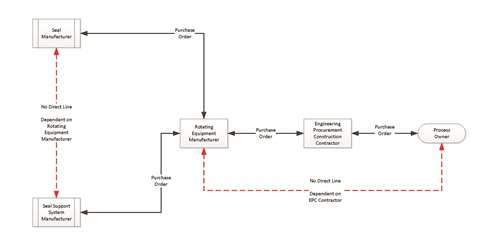 Figure 1: Flow of dry gas sealing system project information
Datasheets typically include detailed, guaranteed and normal operating condition information. Often, several alternate operating points are defined as well. More thought and detail included on the front end of the project can help control costs and prevent changes later in the schedule.
Alternate conditions for dry gas sealing systems
Processes are designed to operate in a steady-state condition with constant operating parameters. However, boundary conditions such as standby, transient, slow-roll, turning gear and settle-out cannot be ignored. These boundary conditions typically influence the selection of dry gas seals and the support system design.
API 692, Annex 2D was developed to assist engineers with dry gas seal selection, while Annexes 2A and 3A assist in the specification of the support system and components.
Influences such as gas sources, ambient conditions, sealing conditions, compressor temperature limits and compressor configuration can determine the minimum and maximum allowable temperatures of the dry gas seal and support system. Most dry gas seals and dry gas seal support systems are rated to the maximum allowable working pressure (MAWP) of the compressor unit. In some cases, they may have different limits than the compressor unit.
The dry gas seal, separation seal and process side seal determine the dry gas seal support system flows. When labyrinths are used in these areas, minimum required velocities across these seals must be considered. A clearance value should be associated with these calculated velocity values. In situations where process gas cleanliness is a concern, these velocity values should be increased.
Seal selection – high or low pressure?
For ethylene producers, there is likely no process that would allow the application of a single seal. The next consideration is high or low pressure. Any process with sealing pressures above 500 psig (34.5 bar) eliminates double-opposed seals as an option.
Multiple refrigeration processes have sealing pressures that operate near atmospheric. However, double seals are not suitable for closed cycle processes. A low or medium pressure body of a cracked gas compressor string might be a good candidate for double seals, but only if a reliable source of nitrogen seal gas is available.
If tandem seals are the only option, then an intermediate labyrinth and secondary seal gas are required to prevent process leakage to the atmosphere. If air is to be considered as a separation gas, then labyrinth-type separation seals should be considered with enough flow to maintain the secondary vent flow below the minimum explosive limit.
Support system module selection
Per API 692, Module A, the alternative seal gas supply provides seal gas during start-up, shutdown and settle-out conditions as the compressor discharge transitions into or out of a suitable seal gas supply pressure.
Choices such as the type, location and orientation of the check valves might affect how well this module performs during these critical conditions. Figure 2 illustrates how a swing-type check valve operates best in the vertical, flow-up orientation, while a piston-type check valve works best in a horizontal orientation.
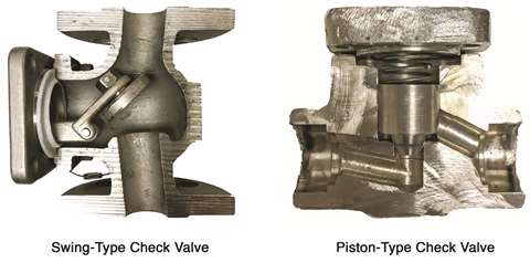 Figure 2: Check valve types and orientation
When merging two independent systems, care must be taken. For example, a nitrogen backup supply could be contaminated by the process gas because of a leaking check valve, which could have adverse consequences. Figure 3 is an example of how to safely isolate these two supplies when the backup supply is at a lower pressure than the compressor discharge.
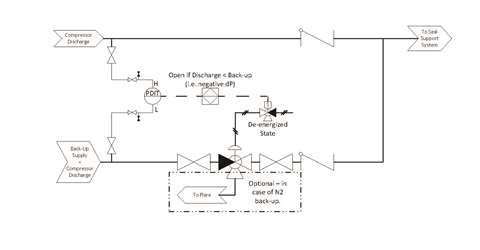 Figure 3: Alternative seal gas supply backup lower than compressor discharge pressure
What if the backup supply is higher than the compressor’s normal discharge pressure? Check valves alone are not the answer. Figure 4 is an example of how to modulate a higher-pressure backup supply, assuming the compressor’s normal discharge pressure is well above settle-out pressure.
The proportional-integral-derivative (PID) control loop modulates the valve until the compressor discharge exceeds the settle-out pressure by a suitable margin (50 psi [3.4 bar]). The backup supply must then be closed off, while the compressor is operating normally and the pressure at the pressure indicating transmitter (PIT) is above the setpoint. These two examples further illustrate the importance of all stakeholders participating in a hazard and operability study (HAZOP).
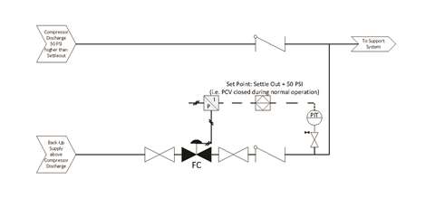 Figure 4: Alternative seal gas supply backup higher than compressor discharge pressure
Based on historical dry gas seal failures, API 692 requires Module B, gas conditioning system (GCS) (as shown in Figure B.18 of API 692) as a default scope of supply for any tandem seal support system to ensure reliability and to prevent costly failures during commissioning and other alternate operating conditions, in addition to normal operation.
Not every module described in API 692 should be considered as a code requirement. The purchaser and supplier should agree if and how a GCS should be implemented, based on the application and previous experience. For example, a cracked gas application has greater considerations with respect to seal gas conditioning than a refrigeration cycle.
Heat Exchanger (B1)
A heat exchanger, although it may be the first component in the GCS stream, is a last resort. A water-cooled heat exchanger increases complexity and could actually decrease system reliability if poorly selected.
Consider the following before committing to a heat exchanger module:
Seal gas supply source, interconnecting piping and ambient conditions. How much variation will there be in gas inlet and outlet temperatures?;
How much “approach” temperature exists between the plant cooling water supply and the desired process outlet temperature?;
Will a 100°F (37.7°C) process outlet temperature be enough to achieve the desired results?;
What is the confidence and level of detail provided in the datasheet process conditions?;
Are there condensable gases that are missing or understated?;
Is cooling fluid on the shell or tube side and can tube leaks be detected and resolved? and;
If a heat exchanger is necessary, then a reliable separator and heater are also required.
Separator (B2)
A separator in the primary seal gas supply is inexpensive insurance against liquids condensing in the seal gas supply piping, which is likely lengthy and uninsulated. For a separator selection to work, condensate collection rates and the specific gravity of the condensate must be considered and agreed upon by all the relevant parties.
Booster (B3)
Just like any pump or compressor, the booster creates flow. The piping system components create the backpressure. Booster devices will not turn a low-pressure supply into a high-pressure supply, regardless of whether they are positive displacement or centrifugal type. They simply create enough differential pressure to provide the minimum seal/buffer gas flow.
In API 692, the minimum gas velocity for the process side seal is reduced when the compressor is operating at speeds below slow roll (500 rpm). While a booster can supply the seal/buffer gas during compressor settle-out or pressurized hold, the specified minimum gas velocity for the process side seal is not expected to be maintained during these periods.
Heater (B4)
As specified in API 692, all seal gas and buffer gas streams (including alternate, backup, and start-up sources) flowing into seal cavities shall be supplied at a temperature providing at least a 20°K (35°R) margin from the dew point line to preclude liquid from entering or forming in the dry gas seal. A heater, heat tracing and/or insulation can keep the seal gas temperature within its limits.
Heat tracing and insulation of lines downstream of the separator must be addressed early on. The seal support system manufacturer can apply heat trace and insulation in the shop environment, but this work could be undone if the system is stored poorly or mishandled later at the site.
The piping designer must leave provision for insulation if it is to be applied later at the site. In some services, where gas is just above the dew point line margin, insulation should start at the gas source as the environment, including rainwater from a summer storm, can rapidly cool the piping, causing liquid to form in the lines.
 Alex Schaefer
Other considerations for dry gas sealing systems
If a tandem seal has been selected, a choice must be made between flow control and differential pressure control. A HAZOP should be performed as early as possible in the project before fully committing to a flow control strategy. This can pay dividends later by preventing changes midway or even late in the project. Input from the rotating equipment and seal support system manufacturer should be sought.
If flow control is chosen, independent, primary supply flow control valves (FCVs) are the optimal choice. Using only one FCV may put the suction side of the compressor in differential pressure control, assuming the seal support system is following minimum velocity requirements.
Not following minimum velocity requirements might eventually show up in the form of poor reliability, but reverse pressurization will present itself immediately. Differential pressure control is a robust control method and, with low signal select properly applied, prevents reverse pressurization of the primary tandem seal in services with low or near atmospheric suction, such as refrigeration cycles.
With respect to alarm and shutdown points, API 692 is sophisticated. With early detection, experienced operators can initiate an orderly, manual shutdown of the equipment in place of an automatic and rapid shutdown. This reduces plant upset and lost product, while increasing the information available for troubleshooting.
 Michael Shaffer
Requirements of API Standard 692
The intent of API Standard 692 is to facilitate communication between the owner, EPC, OEM and any other party involved in the design, manufacture and commissioning of a dry gas sealing system. Advanced planning and mutual understanding and agreement upfront will prevent changes later in the project, keeping quality high, delivery on schedule and costs under control.
Understanding the requirements in API 692 and “applying sound engineering judgment regarding when and where these publications should be utilized” is key to a successful new equipment project or dry gas seal upgrade.
References
American Petroleum Institute, “Dry Gas Sealing Systems for Axial, Centrifugal, Rotary Screw Compressors and Expanders,” API 692, 1st Edition, 2018.
American Petroleum Institute, “Axial and Centrifugal Compressors and Expander-Compressors,” API 617, 8th Edition, 2014.
American Petroleum Institute, “Lubrication, Shaft-sealing and Oil-control Systems and Auxiliaries,” API 614, 5th Edition, 2008.
Alex Schaefer was previously the senior engineer for Elliott’s auxiliary systems product line, including lubrication and dry gas sealing systems. He has served on the API 614 and API 692 Task Force Committees.
Michael Shaffer provides technical support to Elliott’s customer base, service centers and global field service operations. He has served on several API Committees, including the API 692 Task Force.
MAGAZINE
NEWSLETTER


CONNECT WITH THE TEAM