Benefits of advanced machinery for energy storage schemes
21 September 2020
Dr. Klaus Brun and Vishal Jariwala explore why high-performance turbomachinery is so motivated by advanced compressed air energy storage (CAES) technology.
Variable demand on electrical grids results in lower cost or surplus electrical power. Storing this power and holding it for a predetermined time and making it available on demand can significantly improve electric grid management. This is the fundamental premise of energy storage.
Additionally, renewable energy sources like wind, solar and ocean power are increasingly available to supplement conventional fuel-powered electricity generation. The intermittency of their output makes it nearly impossible to integrate them into established electrical grids.
Energy storage schemes can help mitigate this and achieve a lower carbon footprint in electric power generation. Innovative energy storage systems are a key building block for decarbonization and can enable balancing of the supply and demand of renewable energy, stabilizing the grids and reducing CO2 emissions in non-electricity sectors like heating and mobility.
Energy storage aims to affordably store and release energy derived by work and/or heat transfer processes from one instance in time to another. This implies that a typical power generation thermodynamic cycle can be split in terms of temporal sequences of work/heat transfer processes, which enables energy storage.
Customary processes for energy storage systems
Three primary processes are common to all energy storage systems, namely a charging sequence, energy storage and a discharging sequence. Unlike energy conversion systems, these can be scaled independently to optimize the storage system for different applications.
Turbomachines are the main components in charging and discharging sequences for many thermal and mechanical storage schemes. Although a mature technology base for turbomachinery design and development in power generation and process industry sectors exists, innovative energy storage schemes might require customization of this base rather than its direct adoption.
Integrated optimization of thermodynamic processes with the selection of appropriate turbomachinery architectures for affordable energy storage systems is emphasized. Advanced turbomachinery design and manufacturing technologies are recommended for achieving high-efficiency turbines and compressors without compromising life-cycle costs.
Overview of energy storage options
The four main types of energy storage systems are mechanical, electrical, thermal and chemical. Figure 1 shows various energy storage options and their process duration/discharge times and rated power. Each has different characteristics, with the most appropriate energy storage system depending on its desired role in the power management strategy.
Pumped Hydro Energy Storage (PHS)
Pumped Hydro Energy Storage (PHS) is typically used in large-scale, renewable hydroelectric power plants using hydraulic turbomachines for work transfer. In PHS, water is pumped using lower-rate electricity from a lower to an upper reservoir for later use.
The energy is stored in terms of gravitational potential. It is a mature and efficient grid-scale storage option, with many PHS systems over 200 MW installed worldwide. The availability of suitable geographical sites and the possible adverse ecological impact can constrain the application of PHS.
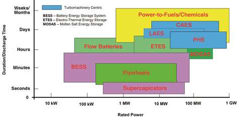 Figure 1. Energy storage options
Battery Energy Storage System (BESS)
This prevalent energy storage system is based on battery technology. In a BESS electricity is stored as a chemical potential, which is converted directly back to electricity as needed. A BESS improves the reliability, availability and efficiency of a grid’s power supply and facilitates the integration of renewable energy in a hybrid power plant.
A BESS is ideal for applications that require a fast response time and demand higher power over a short or medium duration, such as peak shaving, frequency control and load balancing. A BESS can be installed practically anywhere because the batteries are self-contained systems.
Electro-Thermal Energy Storage System (ETES)
An ETES is based on converting electrical energy into thermal energy by storing it in the form of hot water and ice. The thermal energy can be either converted back into electrical power or used for process cooling or district heating. This three-way multifunctional system is scalable, can be used on any site and has a minimal adverse ecological impact.
Molten Salt Energy Storage (MOSAS)
Renewable energy, such as solar thermal, is converted into heat, which is stored in molten salt and used to produce steam for power generation when needed.
The MOSAS solution achieves excellent efficiency because of the high operating temperature and heat transfer properties of the molten salt.
Power-to-Fuels
Power-to-Fuels schemes convert electricity into synthetic natural gas (SNG) or liquids. Commonly referred to as synfuels, these schemes open the possibility of powering mobility, heat and electricity sectors.
Liquid Air Energy Storage (LAES)
LAES is a large-scale thermal energy storage solution that uses liquefied air at cryogenic temperatures as an energy storage medium. Liquid air occupies roughly one-thousandth the volume of gaseous air having the same mass. When re-gasified, liquid air expands rapidly and can be used to run expansion turbines that generate electricity.
LAES systems combine the three existing technologies of industrial gas production, cryogenic liquid storage and expansion of pressurized gases. Although still not adequately proven commercially, LAES is geographically flexible, ecologically benign and energy dense, resulting in a small footprint.
Compressed Air Energy Storage (CAES)
CAES technology is based on the storage of energy as the elastic potential of compressed air. Excess energy, available from the grid, powers the electric motor-driven air compressors to pressurize underground caverns or above ground storage tanks.
The compressed air is traditionally used with natural gas for increased thermodynamic efficiency, but it can also be used by itself where the expansion volume and adiabatic pressure change can generate power in a gas turbine.
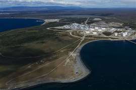
There are currently two first-generation CAES plants in operation, a 290 MW plant at Huntorf in Germany constructed in 1978 and a 110 MW plant at Alabama in the United States constructed in 1991. The CAES option is discussed in more detail in the following paragraphs.
Impact of turbomachinery performance
CAES is a relatively unsophisticated concept similar to a simple Brayton cycle gas turbine engine. Developing an economically viable design with competitive performance for utility grid-scale applications can be challenging.
Figure 2 illustrates a variant of the basic CAES system, along with a typical temporal profile of the stored pressure. This second-generation adiabatic CAES captures the heat of compressed air and stores it in thermal energy storage (TES) for later use when reheating the air during the discharge sequence.
As observed from the temporal profile of the stored pressure, the energy recovery from the stored air must cope with significant pressure and temperature reductions during the discharge sequence. Reheating air and some means of flow and/or pressure control is essential to enable efficient energy recovery.
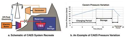 Figure 2. Adiabatic compressed air energy storage
The principal challenge in developing a more economical CAES system is to increase both energy density (ie energy recovered from stored air per unit storage volume) and energy recovery efficiency (ie the ratio of energy recovered from stored air to energy invested in storing and reheating the air).
A simple thermodynamic analysis of an adiabatic CAES system, without any external heating of the discharge air (except for what is captured in the TES at a particular thermal energy recovery effectiveness (Rc)), can be used to illustrate energy recovery efficiency trends.
Figure 3 presents the results from this simplified thermodynamic analysis of energy recovery efficiency (ERE) with respect to turbomachinery polytropic efficiency at two levels of Rc, assuming equal charging and discharging times.
Besides the direct influence of turbomachinery efficiency on ERE, Figure 3 shows the following:
- For turbomachinery polytropic efficiency, ηp ≥ Rc, ERE is nearly independent of stored pressure;
- For thermal energy recovery effectiveness, Rc = 0.6, ERE decreases with stored pressure, and;
- High energy recovery efficiencies (~70%), rivaling those of pumped hydro storage systems, are possible.
These three observations indicate the need to achieve the highest levels of turbomachinery efficiency, especially at low thermal energy recovery effectiveness (Rc). Also, the selected stored pressure has a significant impact on the economics of CAES.
The level of stored pressure strongly impacts the performance and complexity of the turbomachinery, as well as the size of the pressurized storage vessel. Trade-off analyses among costs, performance and operability of the overall CAES plant are required to select the most economic operating pressure levels.
 Figure 3. Impact of turbomachinery efficiency and thermal energy recovery effectiveness
Advanced turbomachinery design for energy storage
In advanced CAES systems, large amounts of airflow at high pressures are required during both the charging and compression sequences. Also, high pressures lead to high operating temperatures exceeding 1,112°F (600°C) and might necessitate more expensive materials.
Various turbomachinery system arrangements and stage architectures are possible. Turbomachinery original equipment manufacturers (OEMs) might be able to customize off-the-shelf turbomachinery solutions for some applications using conventional architectures. The desired levels of turbomachinery performance and operability might not be met.
Figure 4 shows a modern turbomachinery design process, which consists of two interacting phases: design synthesis and design development. The design synthesis phase focuses on innovative solutions to make energy storage technologies such as CAES more affordable.
Design synthesis makes use of creative thinking and experience, in conjunction with soft computing methods such as spreadsheets and machine learning. The outcome is the discovery of the best systems-level solutions, as well as the provision of an initial design configuration to be further optimized within the design development phase.
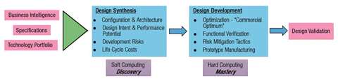 Figure 4. Turbomachinery design process
During the design development phase, advanced computational simulation and geometric design technologies help optimize turbomachinery architecture for the best performance under prevailing constraints, including cost. The physics of flow needs to be resolved to maximize the potential of turbomachinery design.
Advanced simulation techniques are needed to understand and exploit the response of fine-scale flow structures to geometric change. Geometric shaping used in conjunction can quickly drive the geometry towards a preferred target. For example, the use of machine learning.
Manufacturing methods, such as additive manufacturing, can influence the design. Figure 5 illustrates how these tools support the design process.
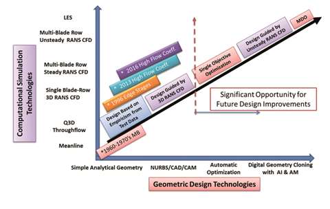 Figure 5. Evolution of advanced methods for supporting design development
The computational cost of high-level flow resolution can be high, but judicious application can be highly beneficial and insightful.
For a large-scale CAES system, multi-stage centrifugal or axial compressors are the most suitable. During the CAES process the heat of compression can significantly increase gas temperatures, which must be limited considering performance and component life cost implications.
Intercooling of gas between stages is typically used to keep the stage-discharge temperatures within a reasonable range. The exchanged heat, if stored in TES, can enhance the ERE. Figure 6a shows a practical approach for achieving this.
Elliott Group manufactures an ISO-cool machine, where the compressed gas is extracted after partial compression for heat exchange. The cooled, intermediate pressure gas is fed back into the compressor to achieve the final discharge pressure.
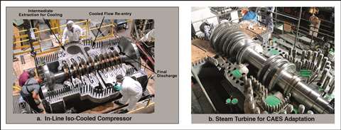 Figure 6. Compressor and steam turbine for CAES adaption
To match the large expansion ratio and the cyclic operation of the air turbine, various innovative solutions are possible. Figure 6b shows an existing steam turbine that an economically viable CAES system can use. Steam turbines are designed for high inlet temperatures up to 1400°F (760°C) or high inlet pressures up to 2031 psi (140 bar).
A power recovery expander stage can also be reconfigured as a CAES system. Rotors and stators, when paired together in a string, create a multistage expansion string. The heat of compression can reheat each expander’s discharge to reheat the air before entering the next expander stage. The CAT-G expander concept exemplifies this.
Conceptual compressor arrangement for energy storage applications Elliott Group and Voith Company have jointly developed a compressor arrangement concept specifically for energy storage applications such as hydrogen, carbon dioxide and air energy methods.
Figure 7 shows this compressor arrangement, which is aimed at high-flow and high-pressure applications. Up to four compressors mounted through a multi-pinion arrangement can run in either parallel or series operation. This concept is designed for optimal rotor speeds, high aerodynamic efficiency and operational flexibility.
Other advantages over conventional multi-body compressor trains include the potential to engage/disengage individual compressors;
- switch between series and parallel operation; allow for multiple intercoolers, side streams, and extractions;
- a compact design with a small footprint, ease of maintenance and repair access, and; elimination of oil leaks into the process gas.
Variable speed is achievable with either a variable frequency drive or a variable speed drive.
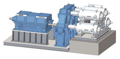 Figure 7. Conceptual energy storage compressor arrangement
Summary
The concept and implementation of energy storage is very important to maximize electrical system use, balance the load on the electrical grid and improve efficiency.
At its heart is the creation of some type of energy potential such as thermal, mechanical, electrical or chemical. Important characteristics of these energy storage schemes are high round-trip efficiency, reliability and affordability.
Research and development is investing many resources to secure the techno-economic position of energy storage in the low-carbon electric grid value chain.
Turbomachinery-based energy storage schemes such as CAES are highly suitable for grid-scale energy storage. Advanced turbomachinery design and manufacturing technologies for high performance, reliability and wide operability can significantly contribute to affordable mechanical/thermal energy storage systems.
A synergistic approach to designing turbomachinery components with well-established OEMs can expedite the integration of energy storage schemes into grid-scale energy storage systems.
 Dr. Klaus Brun
Director of Research and Development (R&D), Elliott Group
Dr. Brun lead Elliott’s advanced development teams for all rotating equipment product lines and related systems, including materials engineering. He joined the company from the Southwest Research Institute (SwRI) where he was the director of SwRI’s machinery program, one of the leading turbomachinery technology R&D programs in the world.
He boasts more than 20 years of experience, which includes an extensive background in aerodynamics, thermodynamics as well as rotordynamic design and testing.
 Vishal Jariwala
Aerodynamics engineer for product development, Elliott Group
Jariwala’s primary function at the Elliott Group is the aerodynamic design of centrifugal compressor stages.
His vast experience also includes centrifugal compressor prototype testing, CFD (computational fluid dynamics) algorithm development and software development.
He holds a BS degree in mechanical engineering from the Regional Engineering College in India as well as an MS degree in aerospace engineering from the University of Michigan in the United States.
MAGAZINE
NEWSLETTER